
Preventing Damage Caused by Ground Loss and Water Loss
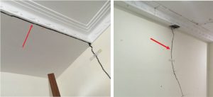
Deep excavation projects in highly urbanized and built-up environments must be designed and constructed with additional care. The design of these projects needs to deal with lateral wall movement, ground settlement, ground loss, and subsurface water pressure changes, all of which can lead to damage to adjacent structures (Figure 1). Damage can be in the form of cracks on non-structural walls (appearance), jammed windows and doors or dysfunctional services (functionality), and, in severe cases, cause structural members to be distressed (safety). Work suspension limits, usually for building settlement and inclinometers, may be breached. The project team could potentially face delays, claims, and additional costs due to expensive rectification work.
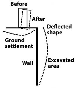
The ground surrounding a deep excavation usually settles. This is due to wall movement towards the excavation when soil is taken out (Figure 2). In design, wall deflection may be controlled by applicable codes. In the author’s region of practice (Asia-Pacific), deflections are limited to 0.5%H (excavation depth) based on BS8002-1994 (British Standard Code of Practice for earth-retaining structures). This also limits the ground settlement behind the wall. However, for deep excavations, the wall deflection is usually controlled by a much smaller limit because of the need to prevent damage to adjacent properties. Another source of ground settlement is from ground loss and water loss resulting from wall leakage and seepage into the excavation. Similarly, a ground loss can develop if fines are washed out when there are gaps in a retaining wall. This article looks at ground settlement as a result of ground loss and water loss in deep excavations.
Building Damage
Building settlement and damage are related. Qualitatively, damage can range from negligible to very severe. Designers should always aim to have negligible damage caused to adjacent properties, although, in reality, it is sometimes complicated to achieve. It is necessary to control ground movement and differential settlement to achieve negligible damage.
During excavation, work suspension limits for building settlement may be set at 0.6 inches (15mm) and 1 inch (25mm) for buildings on piles and footings, respectively. Angular distortion is the differential settlement over length. Generally accepted limits are 1/500 for serviceability criteria and 1/150 for structural damage. The 1/500 target may be challenging to achieve; as a practical compromise, a 1-inch total allowable settlement is commonly adopted for buildings on footings. As an illustration, consider a low-rise house with a 20-foot width (6m) having a differential settlement of 0.8 inches (20mm), which works out to have an angular distortion of 1/300. Therefore, a total settlement limited to 1 inch (25mm) for a footing can be considered a reasonable figure, assuming the differential settlement is a fraction of the total settlement. For piles, the settlement criteria are more stringent. Piles designed to CP4:2003 (Singapore Standard Code of Practice for foundations) have to meet a settlement criterion of 0.6 inches (15mm) at 1.5 times the working load.
Soil Types and Behavior
There are generally two main types of soil behavior specific to clay and sand. In clay, the behavior is undrained. This means that, for an unloading process during excavation, time is needed for the negative excess pore pressure to dissipate. Over time, the increase in the volume of the soil is also accompanied by a reduction in strength. This is why the factor of safety decreases over time. For excavation in very soft soil, there is a tendency for the soil to heave up at the excavated area because of the pressure relief and surcharge behind the wall. In such cases, it may be necessary to improve the soil locally at the excavation base or provide a deeper retaining wall.
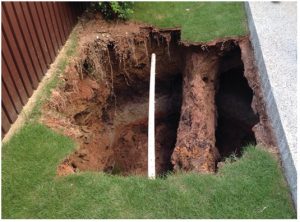
In sand, drained conditions are typically assumed. Due to the high permeability, water can flow easily. This high flow rate enables fines to be easily washed out of gaps in a retaining wall when soil is excavated. When this happens, ground loss occurs and the resulting settlement could cause damage to buildings. Continued ground loss may even cause a sinkhole to form (Figure 3).
Ground Loss
Two types of retaining wall systems that may have gaps are sheet pile walls and soldier pile walls. These are flexible walls and therefore are more suited to excavations that are not too deep.
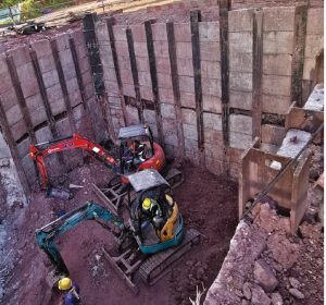
Soldier pile walls are preferred in good ground conditions where the excavation is not too deep because they can be relatively economical, and fast and easy to install. However, the requirement to install lagging in a piecemeal manner means that weak soils and high water tables could pose issues. The soil should have sufficient stand-up time when excavated in small lifts to install the lagging (Figure 4).
For sheet piles, the interlocking joints can be dislodged during installation due to hard driving or obstructions. Re-used sheet piles may have difficulty interlocking due to the distorted edge. In sensitive areas, where vibrations can be an issue (e.g., nearby houses or potential compaction of areas of loose sand), installation should be carried out using a pressed-in method. If hard ground is encountered, it may be necessary to first pre-bore a hole before installation. Any remaining gaps between the sheet pile and the hole should be backfilled with an appropriate material so that the wall can be firmly held in place. Sheet piles can be economical if they are extracted after completion of the excavation. However, it must be noted that extraction in certain ground conditions is difficult without causing excessive vibrations, and the resulting gaps in the ground after extraction need to be backfilled.
Another area where gaps are inevitable is at locations where the wall interfaces with an existing utility (e.g., water pipes, cables, etc.). To prevent washout of fines, it is prudent to provide localized ground improvement (e.g., grouting) or suitable localized lagging details (e.g., steel plate) to close up the gaps.
Water Loss
The groundwater changes around an excavation as excavation proceeds. During excavation, soil and water are removed and the excavation has to be kept dry to facilitate construction. This means that a steep hydraulic gradient is created between the inside and outside of an excavation. Water will find a way to seep into the excavation. Typically, the piezometric levels outside the excavation drop in tandem with the excavation level. The deeper the excavation goes, the more the piezometric level drops. Sometimes, water level decreases may not be significant, so it is essential to look at the pore pressure readings. When there is a soft and compressible layer of soil, such piezometric drops can have very severe consequences. For example, in an area with 13 feet (4m) of peaty clay experiencing a pore pressure drop of 3 feet (1m), i.e., 10kPa, would result in a settlement of 2.5 inches (60mm), assuming mv = 1.5×0.001 kPa-1. This approximation assumes consolidation settlement is the product of three components, namely, the coefficient of volume compressibility, change in stress, and thickness of soil. Volumetric strain is related to stress change by the coefficient mv. Settlement due to the consolidation of soft soils can have far-reaching effects. Experience has shown that houses located at a distance of more than 10 times the depth of excavation can be affected.
Wall Types
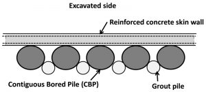
There are various types of walls used to support a deep excavation. However, it is essential to note that retaining walls need to be watertight to prevent water seeping into the excavation. For deep excavation, rigid wall types are typically used, such as diaphragm walls (D-wall), contiguous bored piles (CBP), or secant bored piles (SBP). CBP walls are not watertight, and often secondary grout piles and a lagging system (skin wall) are required to plug the gaps between adjacent piles (Figure 5). Secant piles provide much better water-tightness because of the overlap and overcutting process, but they are expensive.
For very deep excavations, very costly diaphragm walls (D-walls) are typically used. D-walls are watertight, but only if attention is paid to special aspects of the wall.
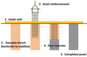
In a typical D-wall installation, the key issues to consider are the guide wall, bentonite slurry, panel size, and stop-end/waterstop (Figure 6). The guide wall helps to provide correct alignment of the wall, and the slurry helps to prevent the trench from collapsing during excavation. Joints between panels must be watertight.
To ensure water does not leak through the panel joints, waterstops are required. Typical details of a waterstop are shown in Figure 7. These rubber strips cut across the direction of the wall joints, thereby preventing water flow. The waterstops are mounted on steel stop-ends during installation to provide rigidity and correct alignment.

The construction sequence involving the waterstop is critical. First, the waterstop is attached to the stop-end. After excavation, the reinforcement cage and stop-ends are installed. Concrete is then cast. The stop-ends are removed after the concrete panel has set and gripped onto the waterstop. Lastly, the intermediate panels are cast and engage the waterstop where it was previously held by the stop-end. Occasionally, the waterstops do not go to the toe of the diaphragm wall. Some waterstops might be terminated at the base slab level or final excavation level. In certain ground conditions, this can be an issue.
There are two primary sources of water loss in a D-wall. First, water can seep through the panel joints below the water-stop. Second, water can also seep below the toe of the D-wall, especially if the soil or rock below the toe is permeable. Therefore, it is essential to understand the ground condition as much as possible when designing a deep excavation retaining system.
Site investigation is required to identify ground conditions and anticipate the issues that may be encountered during construction. For example, in granitic rock and its residual soil, designers need to be aware that soil and rock may be highly permeable. Experience has shown that, at the soil and rock interface, permeability can be quite high. Even when rock is highly fractured with low RQD (Rock Quality Designation) values, water can flow through easily. For such weak rocks, the behavior is dominated by the joints or discontinuities. Similarly, in areas where deltaic deposits are encountered, alternating layers of soft clay and sand may be encountered along with peat, which is very highly compressible. In such ground conditions, designers need to guard against water loss through under drainage and soft soil consolidation giving rise to excessive ground settlement.
It is very important to determine the ground permeability reliably. There are many field tests to determine this, such as a pumping test, a rising head/falling head, and a packer test for rock. Also, a simple particle size distribution test (percentage by mass of particles) can reveal valuable insights about the permeability of a particular soil. A common rule of thumb is that the finest one-quarter of soil by percentage by mass of particles is likely to dictate how the soil behaves mechanically.
Mitigating Measures
Three mitigating strategies to deal with ground settlement associated with water loss are customarily considered.
The first strategy is grouting. Manchette tube or TAM (Tube-A-Manchette) grouting is often used to improve ground conditions. The process is carried out by drilling a hole in the ground and injecting grout, under pressure, in sections sequentially isolated by packers. TAM grouting is carried out at locations where water leakage is suspected, for example, at D-wall panel joints below the waterstop and highly permeable ground below the wall toe. The purpose of the TAM grouting is to seal off leakage locations where water can find its way into the excavation.
In designing an effective grouting process, the designer has to consider the depth, grout type, spacing, pressure, and closely monitor the volume intake and ground movement. It is not uncommon to re-grout the drillhole several times or to have multiple closely spaced drillholes. Close spacing of the drillholes is usually required, e.g., 3 to 6 feet (1 to 2m). TAM grouting is effective because the grout injection fills up voids and pores between solid particles in the ground. Permeability is reduced and groundwater flow is controlled. The strength and stiffness of the ground are also improved. This is why TAM grouting has also been used successfully to strengthen soil below foundations of buildings showing settlement.
Another important strategy to tackle piezometric drops is to activate deep recharge wells. Standard recharge wells are perforated at shallower depths. However, it has been found that deep recharge wells are more effective in channeling water into the deeper soil layers and fractured rocks. Deep recharge wells are drilled into the rock layer and have perforations only at the deeper end of the wells. Volume and recharge pressure is monitored continuously to ensure there is no anomaly. Designers need to be aware that the recharge capability deteriorates over time due to clogging. Therefore, it is important to monitor the performance and implement a periodic cleaning and maintenance regime.
The third strategy is to modify the construction sequence. From the author’s deep excavation experiences, piezometric recovery usually occurs only after the casting of the final level of the base slab. This is because water seepage from the base is cut off more effectively once it is completely sealed. For ease of construction, builders usually plan the excavation sequence such that a large area is excavated as much as possible to facilitate the reinforcement work and formwork before casting of the slab. However, if there is an issue with a piezometric drop around the excavation, then it would be necessary to limit the exposure of the open excavation, i.e., excavation and casting of the slab should be limited to smaller areas and done sequentially. Only after the first portion is fully cast should the second and subsequent portions be opened up in sequence.
Conclusion
In conclusion, the prevention of damage requires stringent control of ground movement and retaining wall movement during excavation. Also, ground loss and water loss should be minimized as much as possible by careful selection, detailing, and monitoring of the support of the excavation system considering the soil types present at the site.■