
Part 2
In Part 1 of this series (STRUCTURE, April 2020), we discussed the Black Box and why it is critical to our work. We concentrated on how to control it in the areas of gross error (total load checks), boundary conditions, and deflections. We discuss load paths, connections, torsion, temperature and shrinkage, and dissimilar materials in this part.
Check Load Paths
Extensive hand calculations forced the engineer to think more thoroughly about providing necessary continuous load paths. While a steel building that is entirely designed in RAM (structural analysis and design software) will have the general load paths taken care of by virtue of the model being correct (if you do not provide the path, the model will be unstable), that fixed-base steel moment frame is going to require some outside-of-the-[black]-box calculations and detailing to get that taken care of. There will be no flashing red light reminding you to do so. Did that super-efficient Excel spreadsheet that the company provided you actually check the shear around the window opening in the shear wall? And if so, did it assume it will be strapped or boundary fastened? Did the software assume the shear walls in the ends of the U-shaped building are one line with a drag connector spanning through thin air? Or separate shear walls? Follow the loads, from the diaphragm to the foundation, to make sure the black box did not create a well-engineered fallacy.
Connections
Connections are everything, right? And unless you are using a specialty connection program like RISAConnection, the program probably is not designing the connection. Further, any seasoned engineer (or steel detailer) can tell you that it is not uncommon for the connection’s geometric requirements to govern the size of the members being connected. Can those one-hundred 16-d nails fit in the connection without splitting the members being connected? Is the footing that “easily calcs out” for bending thick enough to develop the vertical bars extending into the structure above? The black box will not answer these questions for you, so beware!
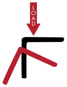
Torsion
Be afraid! Most of us do whatever we can do to make torsion a non-issue. Just put in that extra bracing – it does not cost that much – and then we will not have to check torsion! That being said, torsion may be one area where the black box can actually do better than the average engineer with a pencil and paper. So while you should always keep an eye out for common conditions that can cause a torsional nightmare, if you just model it correctly (and check to make sure it is correct), you will most likely be fine. Step one, make sure the software is checking torsion! Some do not. Step two, with reference back to deflected shapes, do you see the beam twisting under load? Dig into the internal stresses and the reactions being delivered to the supporting member. Is there a moment being delivered due to the torsion? Now, while you are at it, please do a quick check for the following often-overlooked torsional issues: 1) Beams radiused in the plane of the plan always have torsion, so do not calculate them as straight; 2) angles or other odd shapes taking gravity load in bending; 3) steel or concrete beams supporting outlookers; and, 4) sign and sign-like structures that need to receive the American Society of Civil Engineers’ ASCE 7’s, Minimum Design Loads for Buildings and Other Structures, unbalanced wind loading.
Temperature and Shrinkage Effects
Temperature and shrinkage make the most robust concrete crack. They can shatter a weld or pop an embed like it was as brittle as glass. They are almost impossible to resist, so make sure your strategy is to release the system instead. Does that big decorative steel beam that spans between two concrete walls have a slip connection at one end? Does the concrete reinforcing extend uninterrupted through the control joint? What provisions have been made at the reentrant corners? How much internal stress will build up in that long concrete deck with shear walls at both far ends?
Dissimilar Materials
Lots of sleepers here, so when you have dissimilar materials, take the time to think it through. An obvious problem: corrosion. Galvanized steel-to-treated wood. Aluminum-to-stainless steel. But corrosion aside, let us look at how those materials work together. Whenever wood and steel are used together, we have to think about what happens when the wood shrinks (because it will) and the steel does not (because it will not). Big mistakes can be made when designing custom steel hangers for tall wood beams. It is essential to make sure the beam can shrink perpendicular to the direction of the grain without bolts or anything else resisting that shrinkage (and causing cracking). Is there a steel stair up to the 4th floor of that wood-framed apartment building? Or is there a concrete parking structure adjoining it at each floor? Or is there a masonry elevator shaft? The shrinkage of a wood structure can easily be on the order of several inches, depending on how things are detailed, and that tripping hazard could be enough to land a resident on the floor and you in court.
In the upcoming Part 3, we will discuss high-level strategies for the successful use of design software.■