
The City Creek Center’s masonry façade is an example of a structural engineering project that used performance-based-design to improve upon conventional, mundane brick façade systems. Located in Salt Lake City, Utah, the project site encompasses 23 acres of land representing two large city blocks. It contains four residential buildings with 535 units, three office buildings, and 700,000 square feet of retail space. A creek runs through the site, thus the name. The exterior walls of the project are brick, precast concrete, and glass.
Eight architectural firms were involved in the project, but only one structural engineer of record, Magnusson Klemencic and Associates (MKA), Seattle. MKA approached KPFF Structural Engineers early in the project to assist in the design of the brick exterior walls.
As a structural engineer specializing in the design of facades or curtainwalls, including walls constructed of brick masonry, opportunities to design a project of this size rarely occurred during the author’s career. It has been a challenge to convince owners and architects to design brick walls before bidding and show those designs on a set of drawings, instead of specifying performance and requiring the contractor to design the wall. The City Creek project opened the door to this alternative delivery system.
Because of the complexity of the wall, all parties agreed, after much discussion, to include the wall design as part of the project design documents, allowing for a performance-based-design (PBD) method to be used.
Although several different masonry wall systems were used on the project, including reinforced veneer (structural brick veneer), the following describes the innovations on two of the six buildings. For these two buildings, a brick veneer on steel stud system (BV/SS) was selected (Figure 1).

Performance-Based-Design
The advantages of a performance-based-design include the ability to more precisely define the expected performance, increase the chance of achieving that performance, and allow for cost-reducing innovations that deviate from standard practice and/or prescriptive code compliance.
The first challenge was to convince the stakeholders to expand the structural engineering involvement to include performance-based-design. Eventually, all agreed that there were opportunities to customize the BV/SS system to reduce cost and to better meet the owner’s needs. The complexities of the walls helped drive the decision.
Performance Criteria/Expectations
Although BV/SS walls are common, structural engineers typically are not involved in the design except for a limited analysis of the backup wall to determine the expected wall deflection (the codes and standards do not provide consistent criteria for the deflection limit). The applicable building codes for this project were the 2006 International Building Code (IBC), ASCE 7-05, Minimum Design Loads for Buildings and Other Structures, and TMS 402-05, Building Code Requirements and Specification for Masonry Structures. These codes contain limited brick veneer performance requirements, leaving considerable freedom to customize performance criteria.
Early in the process, the Owner, General Contractor, Construction Manager, and consultants were involved in discussions about wall performance. The wind and seismic loads were well defined, but the required performance was not. Since the project is located in a high seismic risk category, the seismic performance was a primary issue.
Seismic loads were divided into three intensity levels; 1) frequent event, 2) 500-year return period, and 3) 2⁄3 maximum considered. The engineer of record provided seismic displacements for each floor at each seismic level. Building wall elements were differentiated by location and geometry – flat or linear walls at the base and typical floors, corners at the base and typical floors, and parapets. Four levels of performance were defined: operational, immediate occupancy, life safety, and collapse.
- Operational (No damage) – Hairline cracking of masonry bed joints may exist, with or without a seismic event.
- Immediate Occupancy (Minor damage, repairable) – Failure of caulked joints and separation of window seals is expected and can be repaired. Cracking of masonry bed joints is expected. Some cracking of brick at corners. Some vertical cracking through brick units is likely but limited. Some separation of face shells from the wall and units from parapets and other appendages.
- Life Safety (Major damage, repairable) – Severe damage to portions of the wall and minor separation from the building, with no panel falling hazard.
- Collapse (Major damage, not repairable) – Large portions of the wall have substantial damage and create falling hazards.
The Table presents the resulting performance criteria for designing each type of wall.

Corner Design
Meeting the operational and immediate occupancy criteria for anticipated damage at the corners of the building presented a design challenge. A typical BV/SS wall would not meet the criteria at the corner. Differential floor-to-floor displacement would break the rigid brick corner. Isolation of brick corners can be accomplished by various strategies:
- Eliminate the brick corner and substitute another element, such as an aluminum plate.
- Provide a large expansion joint at the corner.
- Cantilever the backup system from one floor without attachment to the floor above.
- Build a reinforced veneer or reinforced brick panel that is supported on one floor without attachment to the floor above.
- Warp the backup and brick system by placing the attachment to the upper floor at a defined distance from the corner.
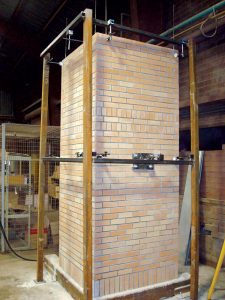
All options were considered. The decision was to use option 5. Options 1 thru 4 could have been developed by analysis without additional technical information. But the information to accomplish Option 5 was not available. Warping the masonry (a panel with 3 corners fixed and the fourth lifted or pushed perpendicular to the masonry surface) is not a common design problem, and no information was available. Consequently, it was decided to test the corner. A mockup panel was constructed and tested to obtain the information (Figure 2). The test demonstrated that the corner criteria could be satisfied.
Brick-to-Building Connection Innovation
For a BV/SS design, the edge of slab detail is important, not only to resist the required loads and accommodate expected differential deflections but also to minimize construction cost. There was a need to improve common details, which usually include slab embedded items that are often not properly located, tilted, and/or missing.
The edge of slab tolerances were defined; in-out (plus or minus ½ inch), up-down (plus ½ inch up and 1 inch down). The edge of slab tolerance is tighter than typical construction but was agreed upon as the innovation of the connection evolved. The up-down tolerance included the effects of the building frame creep and shrinkage.
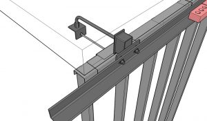
Building floors were 9-inch-thick post-tensioned slabs. Edge forms for post-tensioning typically have round holes for tendons. Placing an embedded bolt in the slab, protruding through some of the holes to connect the brick ledger, would be easy. The bolt could be bent to engage the bottom of the slab form and a coupler added at the end to attach a bracket for a push-pull rod connection to the top of the floor below studs. This eliminated the need for the top of the stud system to have the questionable double-channel detail. The double channel detail is questionable because performance for both in-plane sliding and accommodating differential vertical movement requires careful installation.
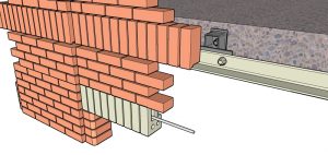
The nominal 9 inches from the edge of the slab to the face of brick provided the opportunity for a custom ledger support bracket. Friction bolt connections were preferred over welding. Vertical slotted holes in the backup plate accommodated the vertical tolerance, and horizontal slotted holes in the ledger accommodated horizontal tolerance. Connections were typically spaced at 4 feet on-center, and the ledger angle was a 3×3×5⁄16 weighing 73 pounds for a 12-foot length (Figure 3).
Reinforced Window Lintels
The design of window and door lintels provided another opportunity for innovation. Typically, bricks above a door or window are supported on mild steel angles designed to a deflection limit of L/600. The angle is exposed to view and becomes an aesthetics issue. Also, there was the complexity of the doors and windows being inset 6 inches from the face of the brick.
Instead of the conventional steel lintel, a structural brick lintel was designed and specified. Figure 4 shows a unique pistol-shaped brick that was fabricated and reinforced with a stainless steel (SS) all-thread (much more economical than SS rebar). The lintel was shored for construction; a panelized lintel was not used due to project space restrictions and lifting limitations.
The Value of PBD
The above is only a part of the innovation applied to these two buildings. There is more, like the design of the thin stone façade at the base of the building and much more on other parts of the City Creek Center project as a whole, including the reinforced veneer (structural brick veneer) on the retail portion of the project.
The City Creek project demonstrates the value of performance-based-design and designing the curtainwall system in coordination with the rest of the design. For the two buildings, a total of 62 full-size curtainwall structural drawings were required. Costs were reduced and performance enhanced. Most important, the inevitable conflicts between parties involved in a complex curtainwall construction project were significantly reduced. The project became a successful team effort.
Curtainwall structural engineering fees, per square foot, are commensurate with structural engineering fees for the primary structure, but the technology and materials can be more challenging. The initial curtainwall design fees may likely be the reason owners do not take advantage of the overall cost savings, which is a lost opportunity.■
This article originally posted as an online-only article in August 2020. The article ran in the May 2021 print issue of STRUCTURE at the author’s request.