
Engineering schools routinely train young engineers in new systems and materials to prepare them to enter the workforce. However, renovations and adaptive reuse of existing buildings are often overlooked or omitted in an already packed undergraduate schedule. The reality of construction today is that there is a high probability that most engineers will, at some point in their careers, work in some capacity on an existing building. Especially in dense urban environments, or in the older parts of the country with a large stock of existing structures, it is often a better use of resources and more respectful of the environment to reuse and adapt an existing building.
For structural engineers, one exciting and relatively common aspect of renovations and adaptive reuse of a structure is when a design requires the transfer of loads from an existing element to a new element. This can be in the form of SCR or “shore, cut, and reframing” of horizontal gravity framing from an existing element to a new element or transferring vertical gravity loads from a load-bearing wall or column to a new transfer element. These alterations often occur when framing for new stair, elevator, or escalator openings where existing beams are shored, cut, and reframed into new girders. Other examples include 1) cutting openings in existing bearing walls and transferring the load to a new transfer beam to create a larger open space below, and 2) cutting a column and transferring the load to new transfer girders to create a larger opening below or to relocate the vertical elements at the floors below. Adaptive reuse of a building that modifies use and occupancy must take into account a column rhythm that may have made sense in the existing building but does not necessarily make sense with the new use. For example, an office building with a regular grid of columns may not readily lend itself to an exhibition space that requires more significant open space.
Today, the design engineer or engineer of record (EOR) would typically first determine the feasibility of the element to be demolished and design the transfer re-support of the existing elements. The engineer would then design and detail the new permanent elements and may provide information and direction on the phasing, sequencing, and means of temporary support necessary to install the new framing condition. Due to the prevalent practice of leaving the “means and methods” of construction to the construction team, which provides for a clear delineation of responsibilities, it often becomes the responsibility of the General Contractor to retain their own structural engineer to develop the final design of the temporary works and transfer mechanism, develop a Method of Procedure (MOP) for the work, and oversee the installation of the temporary works.
Guidance for the design of temporary works and load transfer mechanisms is limited. ASCE Design Guide 37, Design Loads on Structures during Construction (ASCE 37), is an excellent resource for computing practical design loads for temporary structures. ASCE 37 provides the minimum recommended design loads for temporary works; however, there may be some uncertainty of actual loads in older pre-war buildings framed with archaic structural systems that then warrant higher factors of safety. Additionally, strength design may not be the governing case, especially in older buildings with brittle finishes that may require strict deflection criteria wherein the strength design is a secondary consideration. Many practical aspects of this type of work rely heavily on the experience of working with similar structures as well as the knowledge of the fundamentals of structural behavior and the ability to identify and visualize load paths correctly. These skills can be learned from other engineers and experienced contractors who have accumulated this knowledge.
Shore, Cut, and Reframe
SCR is a common abbreviation in modifications to existing buildings. Simple gravity framing that is to be temporarily supported, cut, and then reframed into a new element such as a girder or load-bearing wall can often be supported with adjustable screw jacks with clamps. An adjustable screw jack is a vertical load-carrying member that extends to fit different lengths or heights so it can resolve a variety of situations and can be reused. A typical version of this is a steel pipe column with a threaded bar extender with a wing nut locking mechanism (Figure 1).
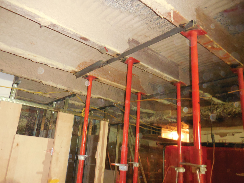
Figure 1. Screw jack set up in preparation for
a shore, cut, and reframe scenario.
Generally, these are intended for light to medium duty installations and vertical gravity loads only. Support at the base is usually with hardwood spreader beams and/or wood cribbing while support at the top can be with clamps, welding to existing steel beams, or spikes fastened to wood beams. Calculation of the loads on the beam to be supported is routine, and ASCE 37 provides guidance on temporary construction live loads. The existing supporting element(s) at the base can be validated with routine design checks, again, using ASCE 37 for guidance, by temporarily reducing live loads to construction live loads. Spreading the load out on heavy timber cribbing over an area can keep the subsequent pressure reaction to the existing documented live load capacity (Figure 2). In an extensive renovation, where the floor beams being supported have been stripped of finishes, and the area is unoccupied, the shoring can be installed and the existing elements can be cut and reframed to the new supporting elements without concern for cracking finishes. However, where working below occupied spaces, including those with brittle finishes, the adjustable screw jack can be slightly overtightened to provide pressure or pre-loading to the element to be supported, before making the cut, to mitigate deflection and potential cracking. Where lateral stability considerations are necessary, diagonal bracing, using pre-manufactured pipe bracing with clamps, works well with adjustable screw jacks. Where loads are high, or heights are significant, it may be necessary to design custom shores, for example, with hollow structural sections (HSSs). Forged wedge shims can be used to achieve pre-loading.

Figure 2. Detail for temporary screw jack set up.
Needle Shoring Masonry Walls
Renovations and adaptive reuses may call for creating new or widened openings in existing stone or masonry walls. Designing a new permanent transfer beam is often the easy part of such endeavors. For load-bearing masonry, steel beams are typically used for their strength, ease of modification, and combustibility considerations. Per the Masonry Society’s TMS-402-16, Building Code Requirements for Masonry Structures, the deflection of beams providing vertical support for unreinforced masonry should be limited to the span, L, over 600. The trickier part of this design is determining and detailing the phasing, sequencing, and means of temporary support to re-support the wall onto the new permanent beam system. Where new openings are modest in size and the existing wall is robust, such as multi-wythe brick with interlocking header or rowlock courses, it may be possible to chip out one side and install a new steel channel header. This allows the rowlock courses to temporarily transfer the load to the remaining solid half of the wall below; the process is repeated on the other side. This approach precludes the need for temporary shoring and is simply a sequenced installation of the new transfer beams in a clever way to save the cost of temporary works. This solution is not recommended for long spans, heavy loads, or relatively weak and thin walls.
Another method to achieve a wall opening is to design temporary transfer beams, commonly a pair of channels that are installed on both sides of the wall above the proposed new opening. This is intended to temporarily bridge the load of the proposed new opening so that the opening can then be safely made and the new permanent transfer beam installed. In this method, the wall load is transferred to the temporary channels via adhesive anchors, through bolts in the masonry work, or by cutting the wall out in small sections and installing plates or tubular sections in small lengths to the underside of the channels.
Figure 3. View looking up at a needle shoring scenario.
However, for heavier loads and longer spans, the optimal method tends to be needle shoring. Needle shoring is a colloquial term used to describe a series of steel beams that are inserted or “needled” perpendicularly through a wall and then supported vertically down to a base such as the ground or temporary footing or spreaders (Figure 3). The needle beams, when adequately spaced, support the masonry wall above through the natural arching action of well-bonded masonry. This allows the wall to be safely removed below the needles for the installation of new permanent support elements.
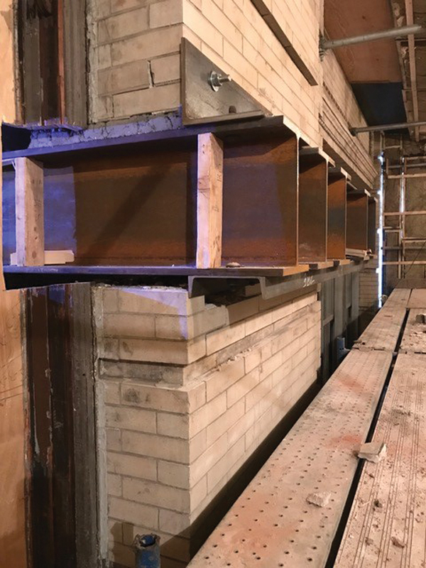
Figure 4. Needle shoring setup. In this scenario, the needle beams are cantilevered from the inside due to site logistics.
The needle beams should be designed for strength and local stiffness requirements, as well as strict deflection requirements, as mentioned above. The procedure generally requires masons to make small openings through the wall, one at a time, to allow the beam to be pushed or “needled” through. The space around the beam, within the opening, is then packed tight with grout and shims for load transfer (Figure 4). Generally, any window openings above are shored with temporary timbers to maintain an even load distribution and to stiffen the openings so as not to put any undue stress on window elements and lintels, particularly if they are stone (Figure 5).
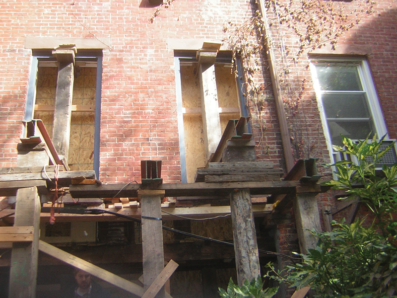
Figure 5. View of rear wall with needle shoring. Note the shoring at the window openings.
Since the arching action requires conservative assumptions, like needle spacing at 2 feet to 3 feet on-center, the vertical support columns below the needle beams create a logistical problem for a contractor to bring in the new permanent steel. As a result, the new steel should be fabricated and brought to the site before the full installation of the needle shoring. This allows for workers on the site to not have to meander through a sea of temporary shoring columns, but rather simply raise the new transfer beam since it is already waiting on-site in position for installation. Otherwise, it may be impossible to erect the new permanent beam around the newly installed shoring.
The transfer of load from the wall to the needle beams always creates the risk of cracking brittle materials like masonry even if the beam deflection is held to L/600 on the new permanent support beam. Where this is a concern, pre-loading of the new permanent beam can be achieved by installing tapered shims between the beam and the wall or, more precisely, via a hydraulic jacking system.
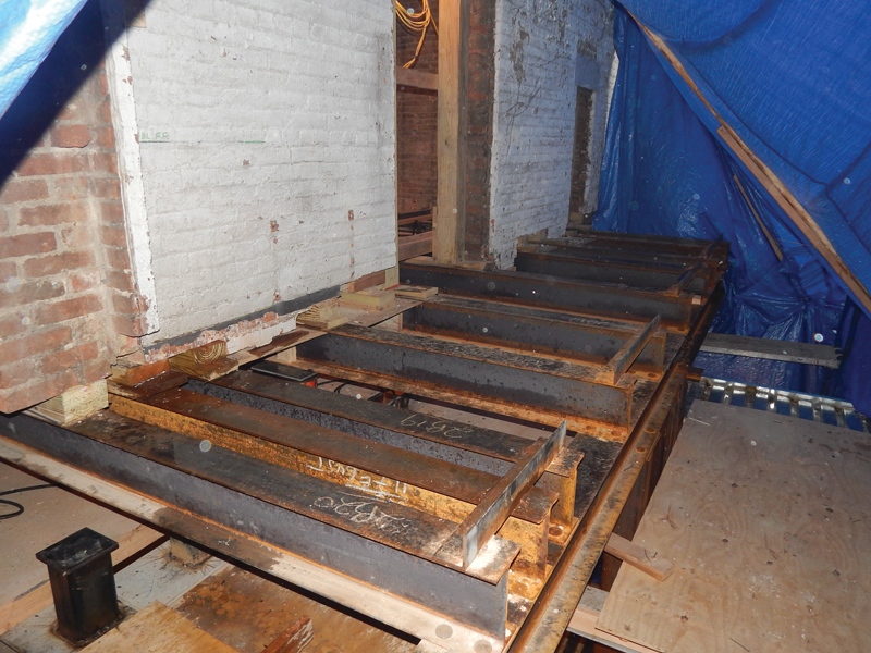
Figure 6. Needle shoring through a brick wall.
The hydraulic jacking system is a simple set up where portable hydraulic lifting jacks are installed between the new permanent beam and the installed needle beams (Figures 6 and 7). The idea is to pump hydraulic fluid into the jacks, which then extend and impart an equal and opposite reaction above and below. The reaction imparted below to the new permanent beam causes the beam to deflect. The reaction imparted above counteracts the existing weight above. Based on experience, pre-loading to 80 – 90% of the realistic dead weight from above has produced excellent results in the author’s practice. More than this could lift the wall, and less than this may not be fully effective in achieving pre-loading. A good way of handling this is to determine 1) the deflection that the permanent beam would see from the new load, and 2) the resulting pressure in the hydraulic gages.
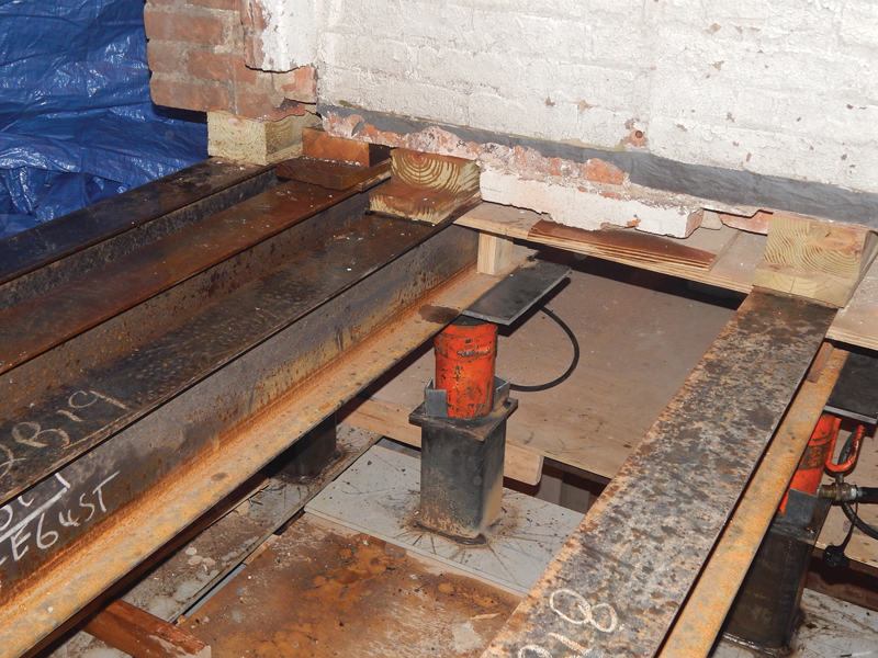
Figure 7. Needle shoring in a masonry wall with a hydraulic jack.
Once the jacks are pumped, the pumping would stop when either the deflection or the pre-determined pressure has been achieved. The deflection can be measured via a laser level. The jacks should each be tied to a gage and tied to a central manifold with a gage so that the total pressure and any individual pressure can be monitored. If all goes according to plan, the small amount of actual pre-deflection cannot be detected without a measuring tape or ruler. Once the pre-loading or pre-deflection has occurred, the needle beams can be removed, and the remaining holes can then be bricked solid to the permanent pre-loaded beam, one at a time.
The key to a successful operation is careful, robust preparation. If the work is done well, at the end of jacking, which may only last a few minutes, an anti-climactic moment occurs where nothing happens. For older materials with uncertain properties and uncertain field conditions, the jacking work must occur when no other work is happening. This allows a team member to listen for any cracking noises and continuously monitor the existing wall and framing for any cracks or signs of trouble. A preconstruction meeting, and a checklist for all parties to review, helps to ensure a successful outcome by avoiding mistakes and keeping all parties safe.
Removing Columns
Most load transfers in older masonry buildings are generally guided by practical considerations and simple engineering calculations with a heap of conservatism to keep problems from arising. Far from rocket science, the processes described above are familiar to any engineer working on older buildings.
In contrast, removing a column from an existing framed building, usually steel or concrete, is a more complicated endeavor. A scenario such as adaptive reuse, say an older office building being converted to a museum or event space, may necessitate some column removals to achieve a new architectural layout.
The basic concept for the safe removal of an existing column is similar to the needle shoring process with hydraulic jacks. The idea is that a new transfer girder or pair of girders needs to be pre-loaded and pre-deflected so that when the column below is cut, the pre-loaded and pre-deflected girders want to rebound up. The remaining column above wants to drop down with equal and opposite forces. This cancellation of forces should result in theoretically zero movements, which, in an existing occupied building, would be the measure of success. See Figure 8 for a schematic setup of a jacking assembly.
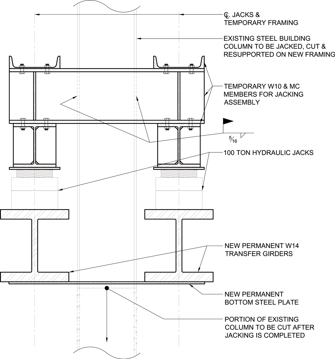
Figure 8. Schematic section at column jacking assembly.
The division of design labor would follow the usual separation of permanent design by the EOR with the means and methods to be designed by the contractor’s engineer. In a steel-framed building, an effective transfer mechanism is to use pairs of transfer girders that flank the column to be removed. A steel jacket can then be designed around the existing column. The hydraulic jacks are set between the transfer girders and the temporary jacket. This allows the jacking to force the girders down using the weight of the column above as a reaction point. Each component of the jacket must be checked for the transfer of load.
Conclusion
The design of new buildings is basically static. New beams and columns are designed for theoretical loads that may happen at very infrequent intervals, and the building is erected from the bottom up. Transferring loads in existing buildings as a result of cutting walls and columns is inherently a dynamic process since the load must transfer from one element to another. In general, the statics and structural analysis are rudimentary; however, planning and method-of-procedure are critically important. Control of deflections through pre-loading is a simple and effective way of dictating how the structural components are to behave to avoid sudden movements and unwanted cracking.
Similar to other aspects of a construction project, the design, detailing, and follow-through for the means and methods of transferring load is a team effort that requires planning and communication with all parties. Perhaps even more than in new construction, a shared understanding of the end goal combined with ongoing collaboration between the designer, the contractor, and the contractor’s specialty sequencing/means and methods engineer is the key to success.■