
Innovation can be a wonderful thing. For engineers, creating, innovating, or even just utilizing others’ new ideas can benefit a client and a project. And many engineers would say that doing something new is almost always more fun than repeatedly reusing old ideas or methods.
For some engineers (the author included), construction using Cold-Formed Steel (CFS) materials fits into this idea of innovation. CFS is a relatively new product line that continues to find more and better applications in the world of construction. The use of CFS in floors is a perfect example.
Technically, CFS has been around for over a century. Since its first use in basic structures and small homes in the 1850s, its use over the next 140 years seems to have been sporadic at best.
Despite the slow start, the use of CFS has grown exponentially over the last 30 years. There are probably very few, if any, architects, engineers, or building officials left who are not at least somewhat familiar with its use. Since the late 1990s, a better understanding of CFS’s versatility and the development of design standards have allowed engineers to specify CFS on projects confidently. The American Iron and Steel Institute (AISI), along with countless engineers, designers, and researchers, have developed and made available CFS standards for use in building design. Technical Notes have been written to address common questions. A few examples of the topics addressed in these Tech Notes include, but are not limited to, avoiding corrosion in CFS members, attachment of CFS to other materials, and design of lateral load resisting elements.
Additionally, multiple software packages now exist to help engineers design anything from the smallest building component to a full CFS load-bearing structure. In short, design resources that were not available previously for CFS products are now readily accessible to assist the design community.
Limitations of Cold-Formed Steel
Projects using CFS as the primary load-bearing material are prevalent in midrise construction and most frequently seen in 5- to 10-story structures, with 10 stories being a widely accepted ‘maximum height.’ However, since CFS is non-combustible, that 10-story height limitation is not due to code; it is only limited by design.
In 2016, the Steel Framing Industry Association (SFIA) commissioned a study to evaluate how high CFS framing could go. Patrick Ford, P.E., of Matsen Ford Design in Waukesha, WI, a very well-known and respected engineer in the CFS design community, developed the SFIA Matsen Tower, a 40-story CFS framed high-rise! The design was even considered ‘conservative,’ and 48 stories has been mentioned as a more accurate limitation.
So how did Patrick Ford develop a design four times taller than the perceived limit? One significant factor was lightening the dead load supported by the walls. A residential structure, such as the theoretical ‘Matsen Tower,’ will need to be designed to support floor live loads of 40 psf. Subsequently, the load-bearing walls need to be capable of carrying this load to the foundation. If a typical floor system, like one using structural steel and concrete, has a dead load of 45 psf, the amount of total cumulative load carried down to the foundation is significant. It is easy to see why CFS construction is limited to 10 stories using this example. The Matsen Tower achieved 40+ stories by using lighter materials for floors…specifically Cold-Formed Steel.
To be a more widely accepted alternative for floors, more versatile CFS systems designed for this application needed to be developed that include the substrate in addition to the support instead of using CFS products as the support for existing substrates, such as poured concrete slabs.
The System
Structural concrete (SC) panels have gained popularity over the past several years as a lightweight alternative to poured-in-place concrete slabs. Depending on the brand of SC panel used, they weigh approximately 5.3 psf and, by significantly reducing the dead loads of the floor, increase the effectiveness of the CFS products supporting them. Much like plywood that is used in wood framing, they come in 4- x 8-foot sheets and are usually ¾-inch-thick. These panels have the strength of concrete, are lightweight, and are non-combustible. Like plywood, these panels may be cut with a circular saw and are screwed to the supporting CFS members. Under standard residential floor load, structural concrete panels require support at a maximum of 2 feet on-center., which corresponds well with the requirements of CFS Trusses and closely matches typical load-bearing CFS stud spacing. For a 26-foot span, a CFS truss with a structural concrete panel floor will have a dead load of only 8.4 psf with an overall depth of 12.75 inches (not including the ceiling).
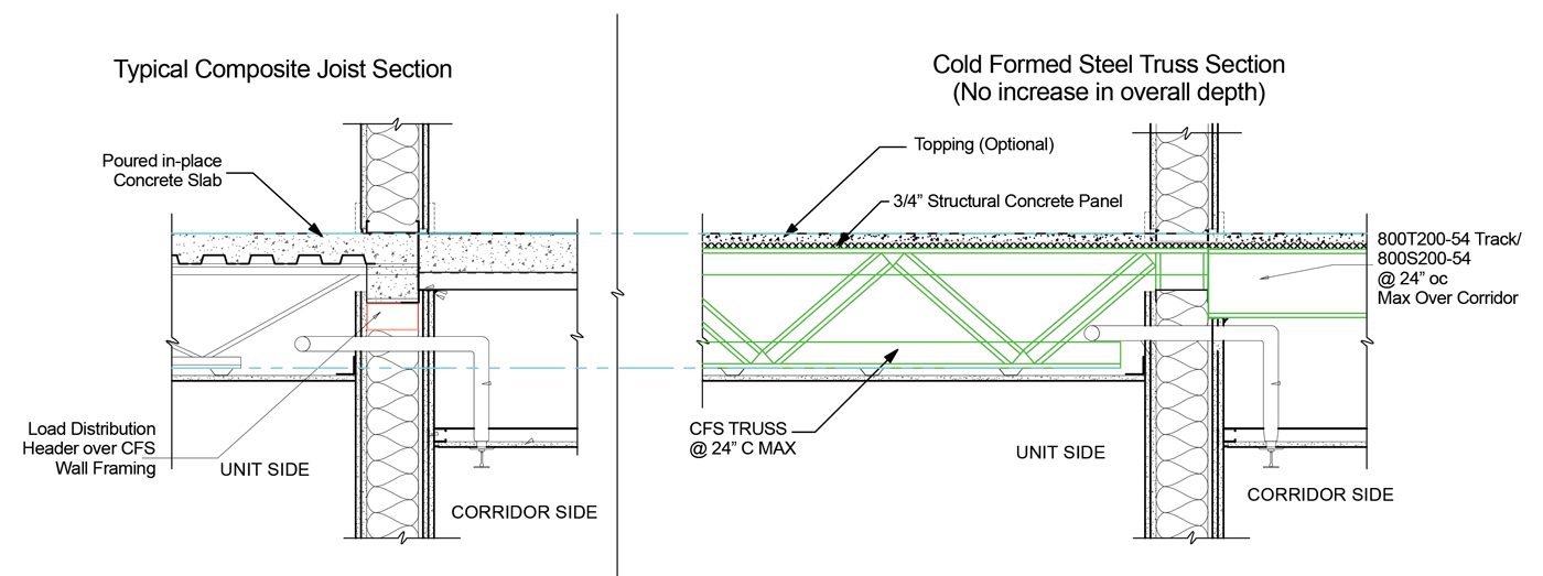
Figure 1. Comparison of typical composite joist section cut and typical CFS truss section cut.
Used together, CFS framing and SC panels can result in an efficient and cost-effective floor system and another portion of a structure that can be designed using efficient CFS construction. The lightweight CFS member supporting the non-combustible lightweight structural panel combine to create an assembly that can be used in place of structural steel and concrete. Spans are comparable to those of composite steel joists/concrete slabs and do not increase the overall depth of the floor system (Figure 1).
Additionally, by saving over 35 psf in floor dead load versus composite joists with decking and concrete and 60 psf versus hollow-core plank, this lighter weight floor system may significantly reduce foundation requirements. The ability to design a lighter weight structure without sacrificing floor depth, load-carrying capacity, or safety is something building engineers often strive for. Building contractors always appreciate systems that allow them to build lighter-cheaper-faster.
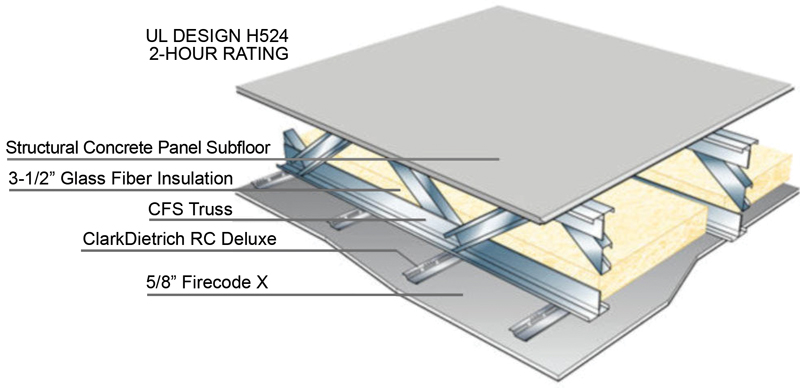
Figure 2. UL H524.
This system has been tested and awarded a 2-hour unrestrained fire rating by UL (Figure 2). In at least one instance, the test only ended due to heat transfer through the floor covering; the trusses remained intact, supporting the full design load. Additionally, it can be installed by the same trades doing the load-bearing CFS wall framing, reducing the potential for coordination issues due to multiple trades required for the framing system.
Designing
Like wood floor truss systems, designing with CFS Truss components is specialized and not something that a building designer should be burdened with. Also, like wood floor trusses, specialized designers and software packages make it very easy for truss manufacturing companies to provide the design of the individual components that make up the CFS Truss portion of the System. A building designer can simply specify loading, spacing, and allowable truss depth, and a truss designer can determine member sizes within the truss components to work for the given criteria. Span tables provided by truss manufacturers can give a building designer basic guidelines for load capacities at specific spans and depths.
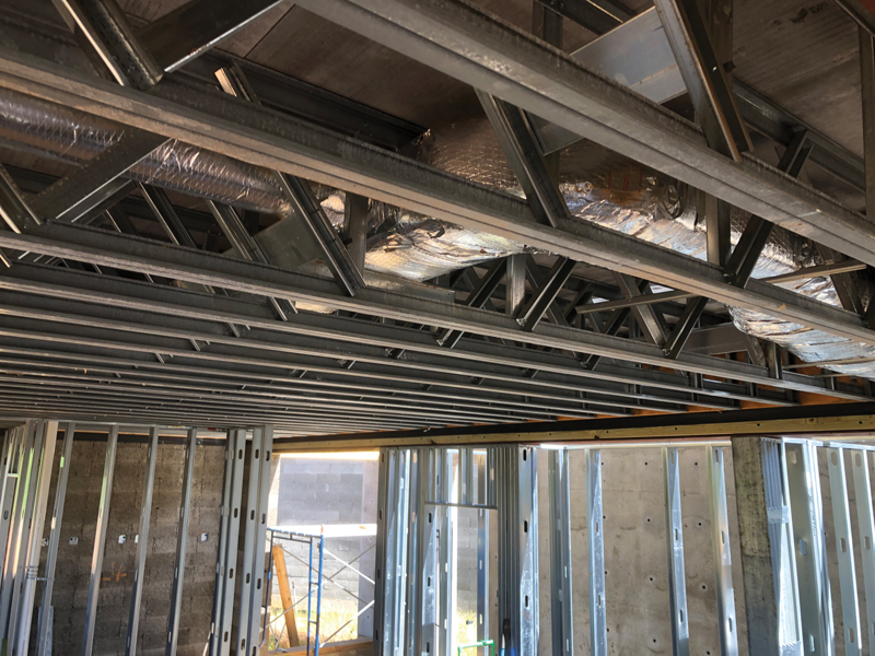
Figure 3. CFS steel floor truss with a structural concrete panel.
Structural Concrete panels attached to CFS Floor Trusses need to be fastened to provide adequate diaphragm strength (Figure 3). The major board manufacturers have done comprehensive testing on their products and have published diaphragm capacities for systems utilizing CFS Trusses and SC panels.
From a design standpoint, it is important to note that CFS Trusses have been used for 30+ years and were initially developed for use in roof truss applications; CFS Trusses in floor applications are more effective and efficient when using CFS Truss Sections that are explicitly designed for that purpose. For example, diaphragm capacities of SC panels are commonly limited by the fastener edge spacing attaching the panel to the truss member. A traditional CFS Roof Truss product will not have adequate flange width to allow required fastener edge distance. Several Floor Specific CFS Truss products have recently come to market considering this limitation and account for this in the truss section’s design.
In seismic applications, the floor system’s required diaphragm capacity can be significantly less with a CFS Floor Truss System versus structural steel and concrete alternatives. The large reduction in dead load using CFS Floor Trusses with a relatively light Structural Panel can conservatively cut story shear in half as it is collected through a structure.
Sound Attenuation
Depth plays a critical role in the design of CFS Trusses. In general, the deeper the truss, the lighter the members. It turns out depth plays a significant role in sound reduction; the deeper the joist or truss member, the less sound transfers between floors. Since trusses can be fabricated deeper than standard joists, a truss may be a quieter option. The spacing of supporting members will also have an effect because sound may be lessened by ‘decoupling’ or creating a separation between the sound and mass in a floor. A wider cavity, or space between joists/trusses, results in a more significant ‘buffer’ or separation between sound transferring members. This is even more advantageous if insulation fills the cavity between joists/trusses. Again, this makes using CFS Trusses beneficial compared to CFS joists. Since trusses typically have more significant load-carrying capacity, they may be spaced further apart than the more shallow CFS joist, increasing the decoupling in a floor system. Incidentally, this also results in fewer pieces to install and easier access for mechanicals. And finally, for improved sound attenuation, it is best to screw the subfloor to the truss/joist support away from the truss/joist web, in other words, as far out on the flange as possible. CFS Truss Chords designed for Floors have a distinct advantage over traditional CFS Trusses used in Roof Construction. The wide flange of these Floor Truss members allows the subfloor to be attached farther from the web, further deadening sound.
History Repeats Itself
It was the 1950s when drywall products were gaining broad acceptance in wood-framed construction but still were not a good option to replace plaster over CMU walls in non-combustible structures. At the time, the United States Gypsum Corporation (USG) had proven the fire resistance of its wallboard products. However, to be successful in non-combustible buildings, they needed a non-combustible substrate to attach to. After researching possible options, CFS proved to be the ideal material, and the Cold-Formed Steel stud wall was born. Fast forward to 2020, and history is repeating, including some of the same players. USG is one of just a few companies that have developed a lightweight, non-combustible floor substrate product. For this floorboard product to be successful, it needs a lightweight, non-combustible, strong, and versatile support. Once again, CFS is proving itself to be the ideal material.
Finally, there is an option for the design community to use Cold-Formed Steel in floors as part of a Cold-Formed Steel structure. It was a long time in development and required collaboration from many product manufacturers – but it will prove worth the wait!■