
Cross-laminated timber (CLT) is taking the building industry by storm and has put wood back into the spotlight as a sustainable construction material that provides occupants with physical and psychological benefits. Its prominence in North America is fundamentally changing approaches to design, manufacturing, and construction. As a relatively new wood product in the United States, design standards and performance-based testing data are lacking or non-existent. Structural engineers are forced to rely on simplified or rudimentary design approaches, particularly when it comes to the lateral design of CLT diaphragms and shear walls.
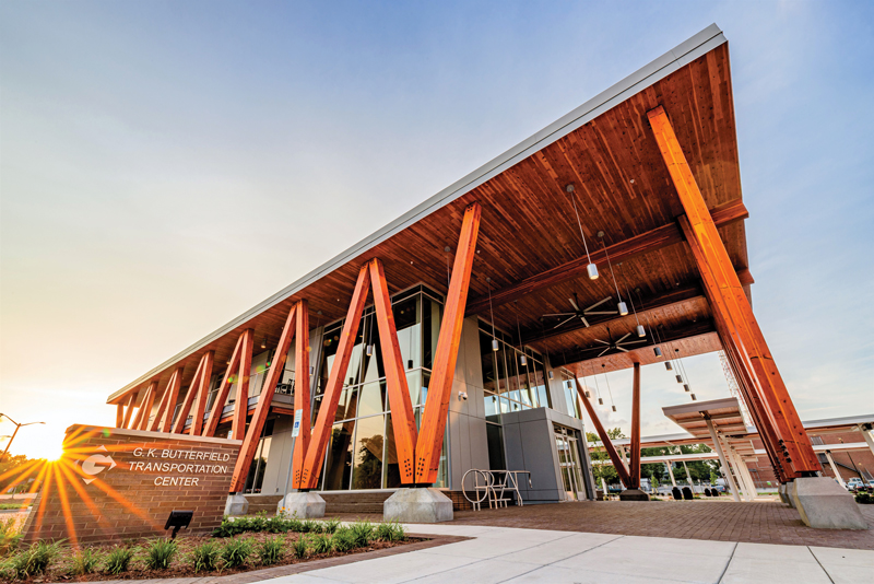
Cross-laminated timber was utilized as the roof diaphragm and shear walls at the G.K. Butterfield Transportation Center in Greenville, North Carolina.
U.S. Design Standardization
CLT was first adopted into the 2015 International Building Code (IBC) and is permitted for use in gravity systems when designed using procedures outlined in the National Design Specification (NDS®) for Wood Construction. Extensive fire testing over recent years has driven wider acceptance of CLT structures among code officials, and the upcoming 2021 edition of the IBC will allow for mass timber buildings up to 18-stories tall. Despite this most recent amendment, the design standards fail to address CLT for use in Lateral Force Resisting Systems (LFRS), and engineers must employ an Alternate Methods and Materials Request (AMMR) to comply with building regulations. Without a prescriptive code path or design standards, engineers have no choice but to rely on overly conservative design approaches or state-of-the-art research with limited data to justify the strength and performance of CLT LFRS. Consequently, local building jurisdictions may be reluctant to allow CLT, particularly in high seismic and wind areas, without a sound understanding of the mechanics-based approach to design.
Lateral Design Principles
CLT diaphragms and shear walls can be effectively designed using a capacity-based approach, similar to other common building materials such as concrete or steel. The premise of this approach is to control the level of force in a structure by understanding performance characteristics and deformation under seismic or wind events. Isolated areas within the lateral system are designed to dissipate energy by undergoing permanent deformation while all other areas are “capacity protected” with overstrength factors. In wood design, connections dissipate energy through fastener yielding using specific failure modes in the NDS. Brittle wood failure modes are avoided. Due to the high in-plane shear strength and stiffness of CLT panels, connection deformation becomes the most significant component of total deformation and the primary influencer of overall diaphragm or shear wall performance.
CLT Diaphragms
Using a capacity-based design approach, CLT diaphragms offer numerous design and construction efficiencies. Currently underutilized by many engineers, in part due to the lack of design standards, CLT panels can be designed as diaphragm chord members, drags, and struts by resisting a combination of bending and axial forces from gravity and lateral loads. Additionally, design professionals may control diaphragm response and performance through proper connection detailing at panel joints and supports, such as compatible deflection or isolation from vertical elements of the LFRS to accommodate lateral drift. Since many of the connections for CLT diaphragms utilize self-tapping screws and other plate connectors, building officials can easily identify and review the lateral load path throughout the construction process.
ASCE 7 Minimum Design Loads for Buildings and Other Structures and the IBC define diaphragm rigidity for the purpose of force distribution to vertical elements of the LFRS, such as shear walls. Based on the interaction between relatively stiff CLT panels and flexible connectors, diaphragms may be idealized as rigid or flexible depending on the type, layout, and stiffness of vertical elements in the LFRS. Using a modified equation for wood panel sheathed diaphragms in the American Wood Council’s Special Design Provisions for Wind and Seismic (SDPWS), flexibility assumptions for CLT diaphragms can be verified using direct deflection calculations. For diaphragms containing irregularities, such as discontinuities or reentrant corners, overall performance and deflection cannot be predicted using simple equations. In these cases, a semi-rigid analysis should be performed using Finite Element models. However, this approach is highly dependent on software capabilities, as well as available product data, and may not be economical or feasible for many projects. For a more prescriptive design approach, it is common practice for engineers to design members and connections for worst-case loads derived from both flexible and rigid analyses while addressing deflection using a simplified approach.
CLT Shear Walls
As with CLT diaphragms, CLT shear walls present their unique design challenges. When subject to in-plane lateral loads, CLT walls primarily engage in rocking behavior due to the high in-plane shear strength and stiffness of the panels relative to the flexible connectors used to adjoin them. Full-scale performance testing of CLT shear walls is limited and focused mainly on tall wood buildings rather than code development for prescriptive design. As such, engineers utilize industry-accepted limits on wall height-to-width aspect ratios to encourage this known “rocking” response. The lag between performance testing and prescriptive design guidance has forced many engineers to fall back on mechanics-based approaches previously developed for wood-sheathed shear walls (perforated, segmented, and force transfer around openings) to calculate CLT shear wall capacity. While these approaches tend to be conservative for CLT, complex force interactions, especially around wall openings, provide a hurdle to prescriptive, yet more precise, analysis methods.
Conclusion
Many notable projects have been completed in the United States, illustrating that CLT is a revolutionary building material for the construction industry with many economic and environmental benefits. However, current design standards are notably lacking, specifically when it comes to the lateral design of CLT. As the mass timber industry matures, architects and engineers must push the boundaries of design with CLT. Investing in additional performance testing and research is critical for the development of tools and resources necessary for more accurate and efficient CLT designs.■
References
ANSI/AWC NDS-2015 National Design Specification (NDS®) for Wood Construction, American Wood Council, 2015.
ANSI/AWC SDPWS-2015 Special Design Provisions for Wind and Seismic (SDPWS), American Wood Council, 2015.
ASCE/SEI 7-10 Minimum Design Loads for Buildings and Other Structures, American Society of Civil Engineers, 2010
ICC 2015 IBC-International Building Code, International Code Council, Inc., 2015
Karacabeyli, E. and Douglas B, editors. CLT Handbook: Cross-Laminated Timber. U.S. Edition. FPInnovations, 2013; co-published by the United States Department of Agriculture Forest Service Forest Products Lab, Binational Softwood Lumber Council, APA – The Engineered Wood Association and WoodWorks-The Wood Products Council.
Karacabeyli, E. and Gagnon S, editors. Canadian CLT Handbook, 2019 Edition. FPInnovations, 2019.