
Creative Use of Structural Steel in a Concrete Structure
The Conrad Washington, DC, the capstone building for the CityCenterDC development, presented several unusual challenges to the design and construction team. The combination of a tight complicated site, the need for large column-free ballrooms, and a below-grade loading dock under the hotel tower compelled the team to selectively use structural steel in a predominantly concrete structure to solve design challenges.
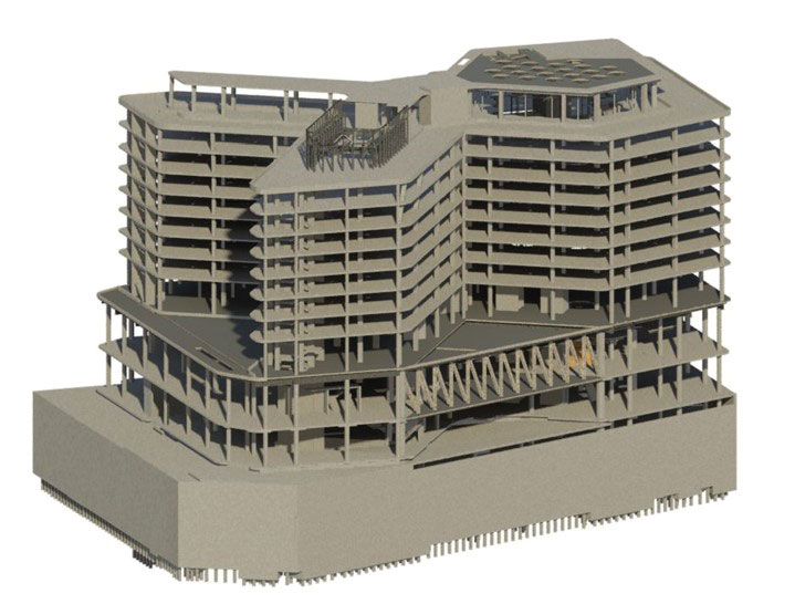
Figure 1. CCDC Hotel structure.
Atrium Skylight
The hotel massing forms a trapezoidal shape for a podium structure up to Level 3. There the floor plate transitions to a pentagon shape around a central atrium with two adjacent 8-story wings featuring post-tensioned flat slab construction at the hotel rooms. The pentagon and wings form a layout reminiscent of an awareness ribbon (Figure 1). The full-height atrium is topped by a skylight and concrete slab, supported by a two-way steel beam system spanning 75 feet by 85 feet (Figure 2). W36 beams spaced at approximately 10 feet in each direction were moment-connected to each other to complete the multi-directional beam system. A portion of the concrete floor slab below was hung from the skylight steel to create an extended slab edge over the atrium at the highest occupied floor. The steel dual-beam system provided minimal structural depth over the long-span atrium.
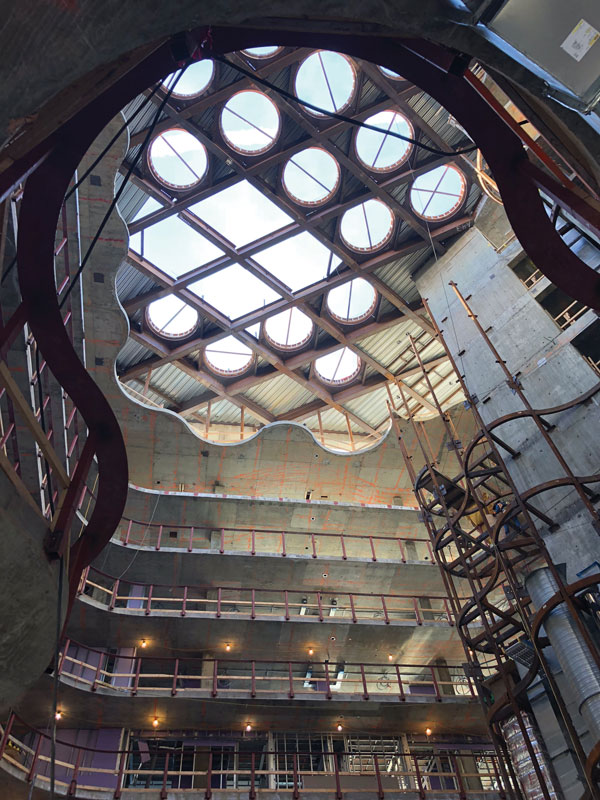
Figure 2. Construction progress and completed atrium and skylight.
Transfer Girders
To fit the full building program on the available footprint and within the design architect’s intent, the design team was required to transfer all but five of the 77 hotel tower columns and many of the concrete shear walls at the third level. To maximize ceiling height within the junior and grand ballrooms, and amenity levels below, the transfer girders were limited in depth to 6 feet. To meet these ceiling height requirements, a steel-framed transfer floor was required with steel plate girders consisting of 4-inch-thick by 4-foot-wide flanges, spanning 55 feet over the grand ballroom and supporting up to four columns. With some plate girder sections weighing over 1,300 pounds/foot, many of the transfer girders required splices with complete joint penetration (CJP) welded and heavy-bolted beam moment connections due to transportation and tower crane limitations (Figure 3).
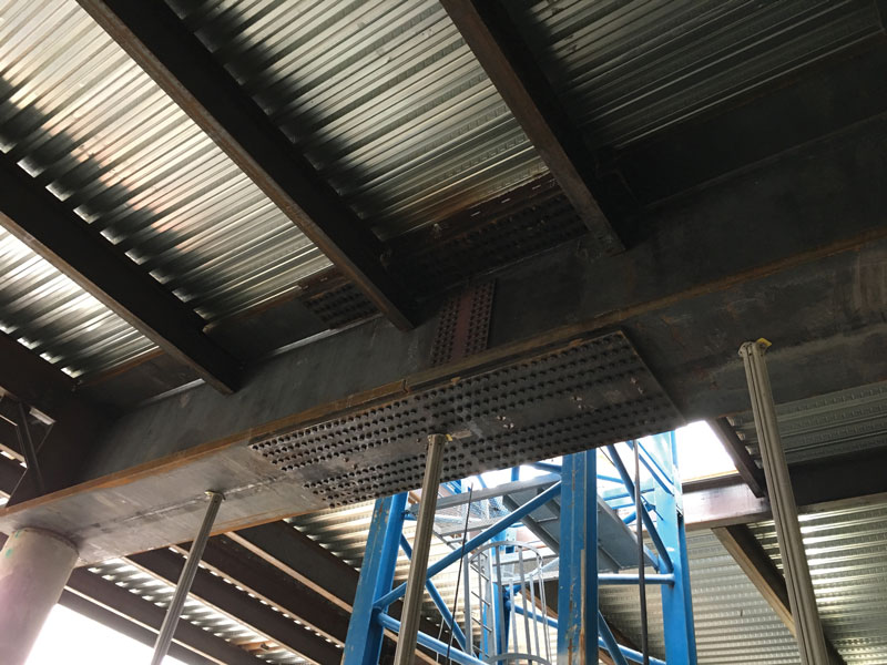
Figure 3. Transfer girder splice.
At steel framing near the tower elevators, the depth of the plate girders was sufficient to accommodate the hotel elevator pits. The pit floors were suspended from the bottom flanges of the plate girders. Vertical reinforcement for concrete columns and walls above were welded to the transfer beam top flange to transfer loads to the podium slab efficiently. Due to the dramatic differences in column arrangements above and below the podium, many framing conditions required cantilevered transfer beams or other unique framing configurations. The unique and deep framing required careful coordination between the architects’ finished ceiling and MEP systems, resulting in many web penetrations through steel members. Perimeter podium columns were tightly spaced and located as close to the perimeter as possible to avoid special framing and detailing of the store-front façade.
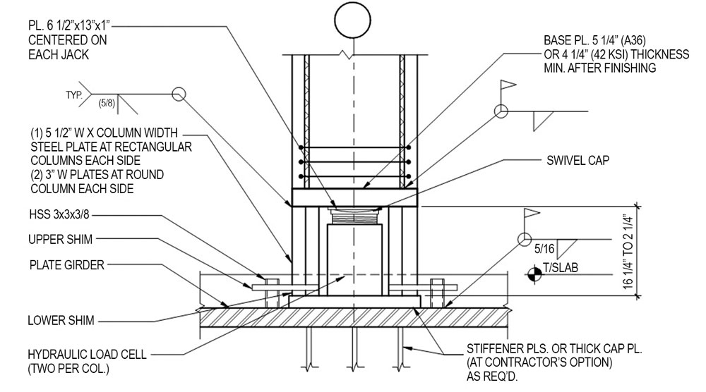
Figure 4. Column jacking details.
The settlement and tilt of the superstructure due to transfer girder deflection had to be controlled during construction. A custom “boot” made of 6½-inch-thick steel plates in a horseshoe shape was designed as the base of multiple columns just above the third-floor framing (Figure 4). The center of the boot created room for two hydraulic jacks while the sides allowed for steel shims to lock the column in place. The settlement at each column was monitored as the above post-tensioned (PT) concrete floors were constructed. As determined by slab analysis of the PT slabs, a displacement threshold of 1⁄8 inch of vertical displacement was used to determine when jacking was necessary. Hydraulic jacks were inserted into the boot, and the entire tower concrete frame was then jacked back to a level condition. The 1⁄8-inch vertical displacement limit resulted in about every third floor requiring column jacking, closely aligning with the structural analysis predictions. Once the concrete tower was fully constructed, steel plate shims were inserted and welded inside the steel boot assembly; the jacks were removed, and the void grouted solid to transfer the final design live load to the supporting transfer beam. The column jacking permitted the use of more economical shallow transfer beams as the majority of the dead load deflection could be jacked back to level. This allowed the slab to be designed for a maximum of L/600 live load column vertical settlement where “L” was the shortest distance between adjacent columns.
Special attention was necessary to coordinate detailing requirements at the interface of steel and concrete, especially at embed plates, bearing plates, and transfer beams, as the different materials had different fabrication and erection tolerances. In most cases, traditional cast-in-place embed plates and beam end connections were not adequate to transfer the high shear loads. Many of the steel beams were detailed to bear directly on a grout pad and embed bearing plate at the top of the concrete columns. For beams with significant end rotation, elastomeric pads were provided below the beam bottom flange to permit member rotation and avoid excessive moment transfer to the supporting column.
The lateral system used to resist the wind and seismic loads consisted of ordinary reinforced concrete shear walls. Due to multiple transfers and offsets in the lateral system, the transfer of large forces through the podium level diaphragm required local slab thickening and diaphragm reinforcement. Despite the low seismicity (seismic design category B), the horizontal out-of-plane offset irregularities and nonparallel system irregularities required portions of the lateral system to be designed considering seismic overstrength, controlling detailing and certain aspects of the lateral design such as collector and chord reinforcement within the diaphragms.
Entrance
A porte-cochere at the hotel entrance is supported by a slab on metal deck, steel framing, and a 23.5-foot-deep, floor-to-floor truss spanning 120 feet located at a reentrant corner of the building (Figure 5). Steel framing at the truss top chord supports up to four feet of soil and landscape plantings on an outdoor terrace above. The truss diagonal members (heavy W14 shapes) were wrapped with gypsum board to provide the required fire-rating and were architecturally expressed as a design feature in the pre-function space of the hotel’s ballrooms. The anticipated deflections for the long span truss required careful coordination with the contractor, particularly concerning curtain wall detailing and construction sequencing. Pre-loading and sequencing of construction options were investigated to determine that expected movements of the truss would remain within the curtain wall design parameters.
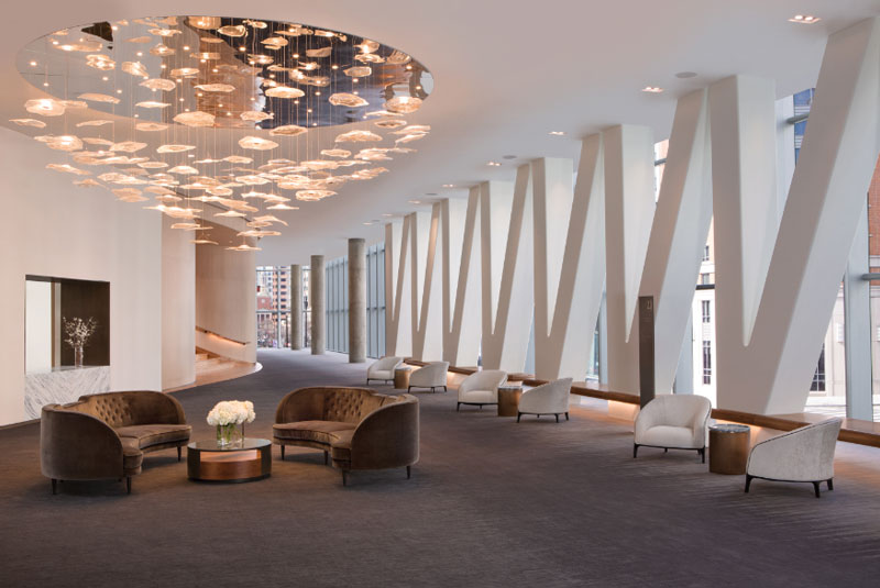
Figure 5. Truss spanning over porte-cochere and supporting the green roof above within the completed prefunction space. Courtesy of Sammy Todd Dyess.
Foundations
The building structure is founded on approximately 1,060 eighteen-inch-diameter auger cast piles. Several pile caps provide support of multiple columns in groups of as many as 66 piles. Many of the pile caps required mass concrete operations and temperature monitoring to control temperature during placement and curing, and to minimize the risk of delayed ettringite formation due to the caps being up to 7 feet thick. Foundations along the property line were designed to accommodate future construction of an adjoining building basement below the lowest level of the building. The lowest level of the garage is 40 feet below the water table. To maintain a dry garage, waterproofing was provided on the outside of the foundation walls, and an underslab drainage system with continuous pumping was installed. A new loading dock and tunnel at the second story below grade connect the hotel to the adjacent CityCenterDC complex. Columns above the loading dock and tunnel were supported on 4-foot-wide by 10-foot 10-inch-deep concrete transfer beams spanning 74 feet to allow for truck access to the loading dock. The concrete transfer beams required the use of mechanically spliced 75 ksi rebar utilizing multiple layers of top and bottom steel.
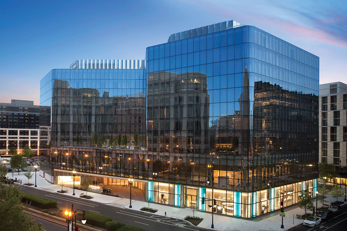
The Conrad Washington, DC. Courtesy of Sammy Todd Dyess.
The below-grade levels are two-way conventionally reinforced concrete slabs with beams at specific locations for parking, loading docks, and mechanical spaces. Access to the parking levels is made through a corkscrew ramp at the northeast corner of the site. The ramp interrupts floor diaphragms that provide lateral support for the basement walls. Special analysis was required at the ramp and adjoining slabs to ensure lateral loads from the basement walls were resolved at the interrupted diaphragms. The section of the slab between the corkscrew ramp and the foundation wall was reinforced as a horizontal wall beam to span the entire ramp width laterally.
Conclusion
The creative use of structural steel (1,368 tons) in a predominantly concrete structure was critical to meeting program requirements and the architect’s design intent and essential in delivering the project on time. Careful detailing at the steel and concrete interface was required to accommodate different construction tolerances and large force transfers. Additionally, due to the complex massing transition, many types of advanced analysis were necessary to provide an optimal building structure.■