
Viscoelastic Coupling Dampers
Tall building designers are increasingly facing challenges related to wind and earthquake-induced vibrations, especially as buildings are built taller and more slender. Frequent windstorms can cause lateral accelerations, which can result in occupant discomfort. Rarer, more severe windstorms and service level earthquakes (SLE) produce large loads in the structure that have to be resisted elastically by the structural members. A primary cause of these vibrations is the low levels of inherent damping (the ability of structures to absorb vibrational energy and slow down dynamic vibrations) in taller structures. Furthermore, severe earthquakes can cause distributed damage throughout the entire structure in conventionally designed buildings, putting in question their post-earthquake safety and use.
Damping Systems
Damping systems for tall buildings are classified as distributed damping systems (typically viscoelastic or viscous) or vibration absorbers (typically tuned mass dampers or tuned sloshing dampers). Vibration absorbers are large masses at the top of buildings that, when “tuned,” transfer a portion of the energy from the building structure to the vibration absorber. These systems are only tuned to the fundamental lateral modes of vibration and are typically only relied on for reducing frequent wind vibrations. This is due to their reduced effectiveness beyond their tight-tuning range and because of maintenance requirements, such as monitoring water levels or checking waterproofing for a tuned sloshing damper or inspection of mechanical components in tuned mass dampers. The most significant overall impact on a project is that they occupy large valuable space at the top of buildings.
Distributed viscoelastic and viscous dampers are activated through relative movements induced between structural members when a structure sways under wind or earthquake loading. When they are optimally configured and designed, they can increase damping levels in building structures in both fundamental and higher modes of vibration and thus be effective for all dynamic loading conditions.
Viscoelastic Coupling Dampers (VCDs)
Distributed dampers have historically been configured in shear-type frame buildings either as braces or vertical damping panels, which are engaged by inter-story racking of the structure. This is efficient and practical for low rise steel frame buildings, but today’s tall and slender reinforced concrete (RC) buildings behave more like cantilevers under lateral loads. The lateral load resisting systems of tall buildings are now primarily formed by vertical structural elements coupled together with coupling beams or outriggers, which are deformed and stressed in vertical shear. Those heavily stressed coupling members are ideal locations to configure dampers to add distributed damping to high-rise buildings to reduce wind and seismic vibrations. These features led to the development of the Viscoelastic Coupling Dampers (VCDs) at the University of Toronto in collaboration with Nippon Steel Engineering and Kinetica (Figure 1).
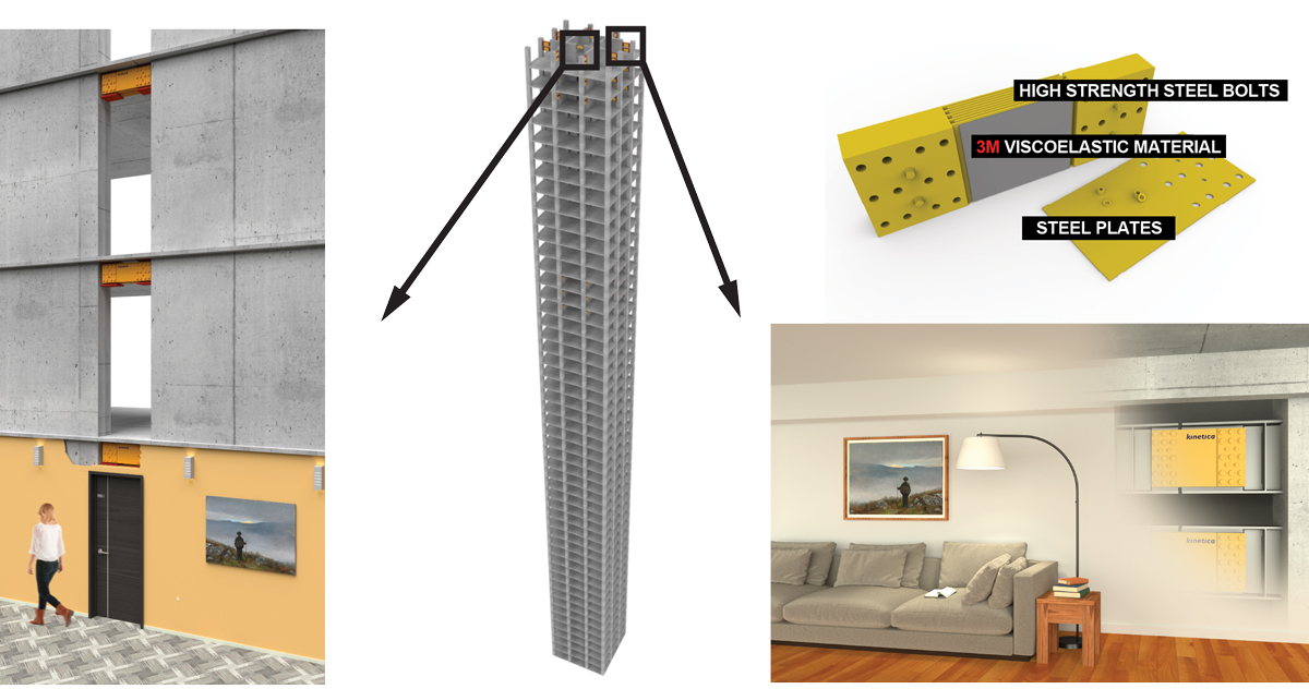
Figure 1. Viscoelastic coupling dampers.
VCDs consist of multiple layers of solid viscoelastic (VE) material sandwiched between and bonded to multiple steel plates. Each consecutive steel layer is extended out, connected to the opposite side, and anchored to the structure. As buildings deform due to lateral vibrations, the solid VE material layers are sheared in-between the alternating consecutive steel plates, providing instantaneous elastic and viscous forces. VE material can be modeled simply as a spring and dashpot in parallel. The force in the VE material, FVE (t), at a time, t, is expressed as FVE(t) = kVE uVE(t) + cVEu˙VE(t), where uVE(t) and u˙VE(t) are the shear deformation and deformation rate, respectively, at a time t, while kVE and cVE are the VE material stiffness and damping coefficients. Figure 2 shows the deformed shape of a coupled tall building with the solid VE material being sheared vertically and dissipating lateral vibrations.
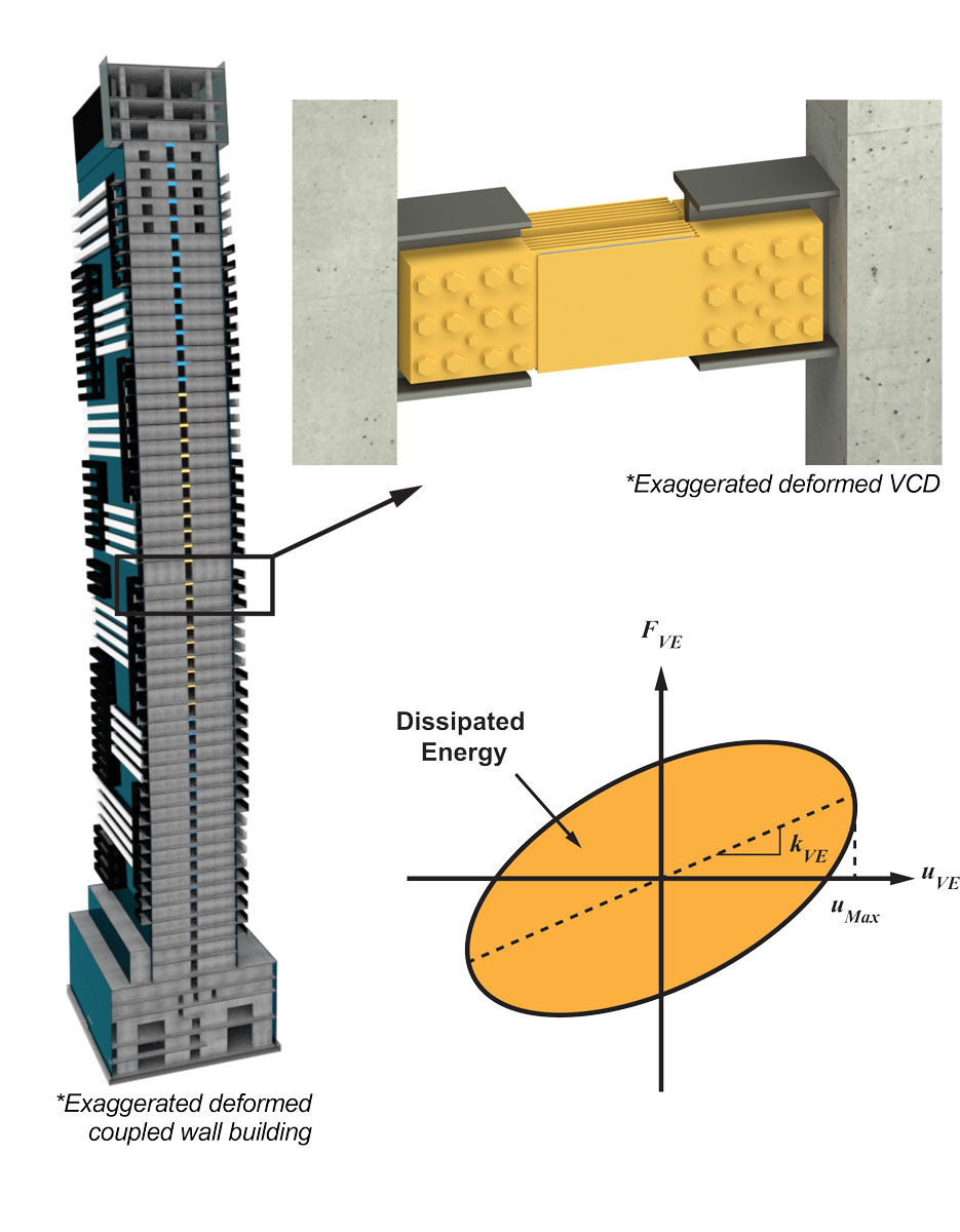
Figure 2. Coupled wall tall building structural kinematics.
Because the solid VE material is rigidly connected to the structure and the damping mechanism does not rely on mechanical components or pins, the solid 3M™ VE material dissipates energy at the molecular level. It, therefore, provides instantaneous viscoelastic response even for very small deformations. Tests conducted at the University of Toronto showed that the solid 3M VE material used in the VCD provided a viscoelastic response even for deformations of +/-0.003mm or +/- 0.00011 inch. In seismic areas, where the building could be subjected to a rare earthquake, whereby drifts can become very large as the amplitude of vibrations is increased, the connecting steel members are capacity designed to yield. This adds even more energy dissipation, and capacity protects the remaining structure. This unique feature allows the damper to be used efficiently for all loading scenarios, frequent windstorms, severe windstorms, and frequent earthquakes through to Maximum Credible Earthquakes (MCEs).
The solid 3M viscoelastic material was the first damping material used in structural applications dating back to 1969 and has been utilized in 300 buildings in some of the world’s most severe wind and seismic regions. There is no requirement for maintenance or monitoring because of the excellent aging and fatigue characteristics of the 3M VE material.
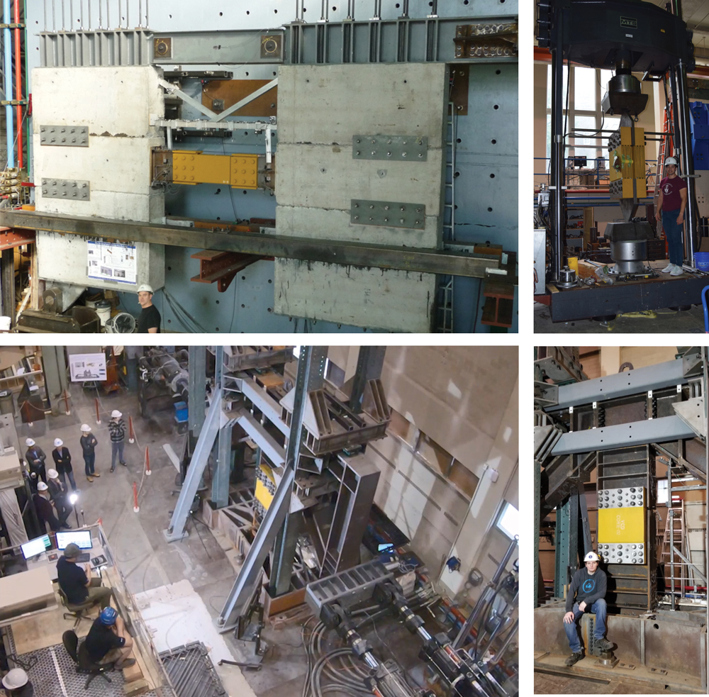
Figure 3. Full-scale uniaxial and shear racking VCD tests at the University of Toronto.
At the University of Toronto, the 3M VE material has been thoroughly tested to confirm its mechanical properties, which agreed very well with the manufacturer’s stated properties. Also, multiple full-scale VCD test specimens, manufactured by Nippon Steel Engineering, have been tested uniaxially, confirming the scalability of the material properties. Multiple full-scale VCDs have been tested in two different racking configurations to confirm the overall system performance (Figure 3).
Examples of Design with VCDs
The following are projects where structural engineers have used the VCDs to create value for their clients, in wind-critical regions, seismic-critical regions, and combined wind and seismic-critical regions throughout the world. In all instances, the VCDs have allowed engineers to meet design targets economically and improve the dynamic performance of the structure. All buildings were designed and analyzed using typical commercial software, such as ETABS, SAP2000, or Perform-3D. Linear springs and dashpots were used to model the mechanical VE damper behavior. Every VCD project has a robust QA/QC program provided by the damper manufacturers, Nippon Steel Engineering and 3M, including VE material tests and full-scale VE damper panel production tests.
YC Condominiums, Toronto, ON
Yonge College (YC) Condominiums is a 66-story, slender residential tower (11-to-1 slenderness) in downtown Toronto, where limiting wind vibrations caused by frequent windstorms was a crucial aspect of the structural design. The developer’s mandate for the project was to maximize sellable space within the prescribed architectural height, which determined the choice of damping system for the project.
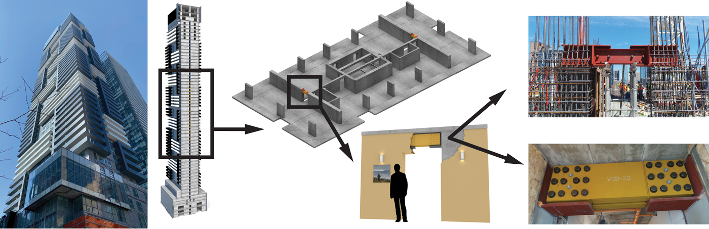
Figure 4. VCDs in Yonge College condos.
In the narrow plan direction, which was critical for lateral vibration, the lateral load resisting system consists of two primary coupled RC shear walls, along with an RC core and columns (Figure 4). Wind tunnel studies indicated that the building would require a supplemental damping system to be added to increase the damping in the fundamental mode of vibration to improve the level of human comfort for 1 in 1-year and 1 in 10-year wind-induced motions. Two damping systems were considered: i) distributed Viscoelastic Coupling Dampers (VCDs) and ii) a bi-level Tuned Sloshing Damper (TSD) tank. The building developer selected the VCDs for the project after a detailed comparative technical and financial analysis of the two systems. A primary advantage of the VCDs was the fact that they were integrated within the structural system, resulting in an additional 5,000 square feet of usable penthouse real estate. Another consideration was that there was no tuning or monitoring, and there was no long-term maintenance plan required for the VCDs to ensure performance.
The structure used 84 identical modular Viscoelastic coupling damper panels, produced by Nippon Steel USA and 3M. Each VCD consisted of 2-VE damper panels bolted to cast-in-place steel embeds. A total of 42 VCDs replaced 42 RC beams on 21 levels of the structure. Figure 5 shows the implementation of the dampers in the project. During erection and concrete casting, temporary steel channels were used where the dampers were to be installed to ensure the correct VCD placement. After the building envelop was completed, a small three-person crew of ironworkers removed the channels and installed the VE damper panels with a slip-critical bolted connection. Drywall was then installed over the VCDs.
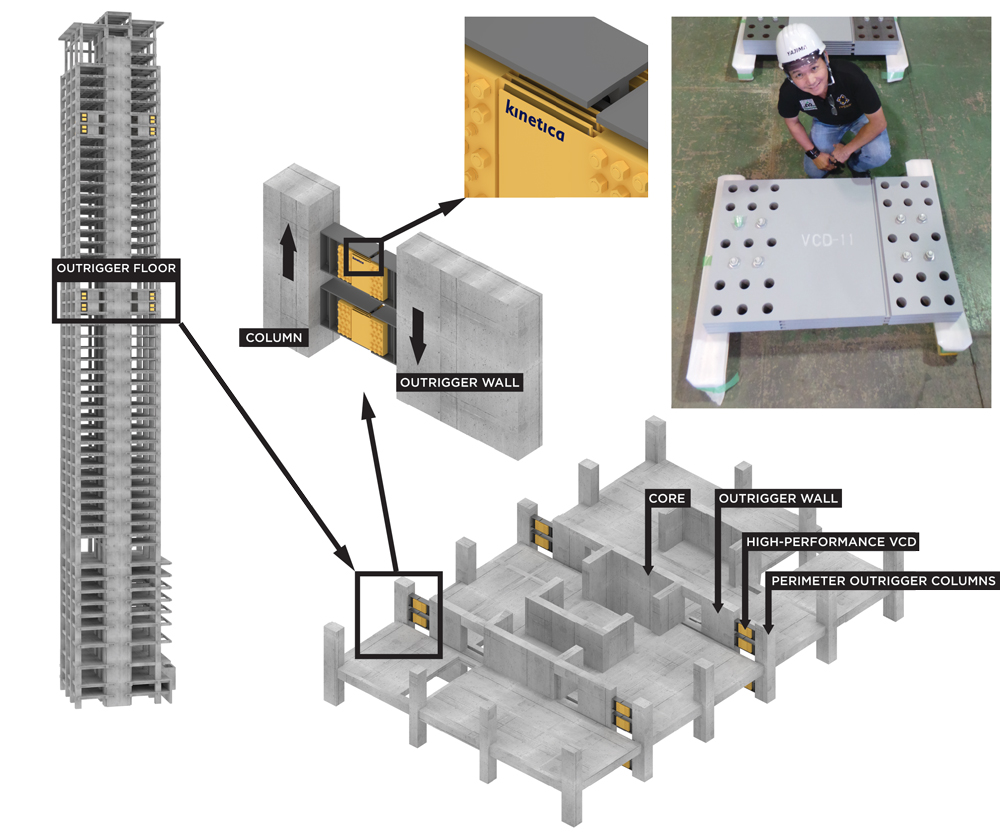
Figure 5. Damped VCD outrigger configuration.
The wind tunnel results required an added 0.9% damping in the fundamental mode of vibration. Each VE damper panel consisted of nine (9) VE material layers, each 5mm-thick, bonded between the steel plates. The VE dampers were modeled with a spring and dashpot in parallel and configured into the Engineer of Record’s (EOR) ETABS models. The added damping was assessed using free vibration analyses. Free vibration is readily implemented by inputting a lateral push to the building, holding it there, and releasing the load, and then measuring the reduction in peak cycle amplitude over multiple cycles of vibration.
During construction, the dynamic characteristics of the structure were monitored with accelerometers as the project progressed; localized displacement measurements of the dampers were also taken to study the robustness of the damping system and to compare the in-situ building behavior to the models. Monitoring showed that the predicted added damping was slightly exceeded during a service level event (5-year return period). Also, the kinematic behavior predicted by the EOR’s ETABS models was accurate even though the building period was shorter than that considered for the wind tunnel studies, and the peak modal amplitude of vibration during the storm was only 80 mm (approximately 3 inches).
Outrigger VCD Configuration
Recently, the VCD system was used in south-east Asia in nine tall buildings (Park Central Towers 1 and 2, Seasons Residence Towers A, B, C and D, Connors Tower, and ParkLinks Towers 1 and 2), where the VCDs are intended to improve both the wind and seismic response of the structure. The general design approach in these areas is to conduct a conventional code design for wind and non-prescriptive performance-based design using the PEER-TBI and the Los Angeles Tall Buildings Structural Design Council (LATBSDC) guidelines. Because of the significant wind demands, outrigger flag walls are commonly used to increase the stiffness of the lateral load resisting system to reduce wind drifts. The flag walls consist of heavily reinforced concrete beams spanning over the corridors and framing into an RC wall that runs between two residential units. During rarer design level events, such as service earthquakes and design windstorms, the RC beams are designed to remain linear elastic; during rare earthquakes, those RC beams are designed as structural fuses to prevent overload of structural columns and outriggers. Because of this design intent, the beams end up being very strong to resist wind loads; during MCE events, they introduce large shear forces into the core and large axial forces in the columns. The beams are expected to be mostly damaged because of the significant combined axial and shear demands.
VCDs are introduced connecting the RC flag walls to the columns with ductile detailing of the steel connecting elements, following general requirements prescribed in ASCE-341, Seismic Provisions for Structural Steel Buildings, seismic details for Eccentrically Brace Frames (EBF) steel links. The flag walls and columns are capacity-designed to accommodate expected overstrength in the ductile members (Figure 5). A slotted connection is provided in the damper panel connection to allow for differential settlement between the core and the columns if required. Under more frequent windstorms, the dampers add significant damping to the system and reduce drifts. Under design level wind or service level earthquake events, where the structure is intended to respond linearly elastic or essentially elastic, loads are reduced, resulting in structural efficiencies. Under more extreme events such as Maximum Credible Earthquakes (MCE), the ductile connecting elements can yield reliably, ensuring columns, flag walls, and corridor beams are not damaged. This results in reduced loads on the RC core and columns because of the added damping and a gentler stiffness transition compared to the RC flag walls. It is also a more reliable ductile mechanism compared to the conventional flag wall RC beams. In addition, because of the increased wind and earthquake performance, a number of developers have also advertised the use of the VCDs to emphasize higher structural performance, garnering an estimated 5% additional revenue.
630-meter Seismic-Critical Building in Southeast Asia
A 110-story, 630-meter mega tall building, with a total gross floor area of more than 330,000 square meters designed in a highly seismic region in Southeast Asia, has been redesigned with the VCDs (Figure 6).
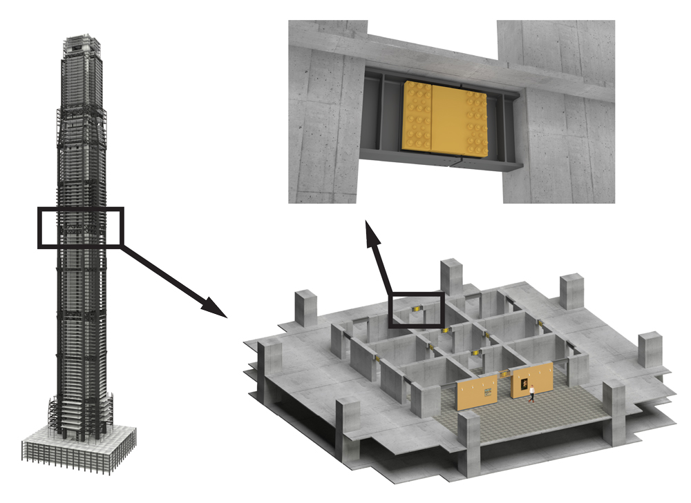
Figure 6. Megatall building equipped with VCDs.
Even though it is a mega tall structure, the design of the building was governed primarily by seismic loading using a non-prescriptive performance-based approach with PEER-TBI and LATBSDC guidelines. The primary lateral load resisting system consists of a coupled core wall (RC) and a steel truss outrigger system that connects the core with the super columns. There is a secondary lateral load resisting system consisting of a mega frame comprised of the super columns and belt trusses along with the steel truss outrigger system.
Due to the importance of the tower in the region, size of the tower, and seismicity of the site, there was a desire to improve seismic performance and reduce the cost of the lateral load resisting system. Two design challenges included the large core shear forces requiring significant reinforcing and large overturning moments requiring extremely deep mat foundations. The redesign consisted of the VCDs replacing about 60% of the diagonal RC coupling beams in the core throughout the height of the building, with the VCDs locations optimized for performance with Perform-3-D results targeting the large shear forces and overturning moments. The VCDs provide significant levels of added damping in the first modes of vibration, which reduces the overturning moments. The VCDs also provide added damping in the higher modes of vibration, which reduces the core shear demands significantly. The upfront financial benefits are substantial, with a significant reduction in structural materials and approximately 6 months of expected construction time savings primarily because of reduced complexity of the reinforcing and member size reduction. In addition, because of the added damping and the fact that the VCDs are replacing structural members that are expecting to be heavily damaged during an MCE event, the VCDs inherently increase the resilience and expected damage for all earthquake levels. Also, the use of the VCD enables the developer to market the resilience improvements that are achieved, which is expected to result in increased property value and revenue.
Looking Forward
Tall building design is continuing to evolve, and the VCD is a tool that structural engineers can use to solve dynamic loading challenges as designs push new limits. As a robust wind and earthquake damping system, VCDs can be readily implemented by using tall building structural design tools such as commercial software platforms, wind tunnel testing, and performance-based design, resulting in significant structural performance and cost-effectiveness of high-rises.■
Structural Engineer Project Teams
ARUP, Magnussen and Klemencic Associates (MKA), PT Gistama, Read Jones Christoffersen (RJC), SY^2, and Thornton Tomasetti (TT).