
Canopies can either be free-standing structures or can be attached as a structural component to a main building structure. They can be situated at an entrance of the building, acting as awnings, or they can be located anywhere along the face of the building up to the roof level. Canopies are not only used for protection of the entrance from dust and rain but also to increase the aesthetic appeal of the overall structure by either becoming integrated into the building or by highlighting it. Hence, there is a need to economically design the size and shape of the canopy and its connections.
Codes governing canopies provide limited information dedicated to the design of canopies. For example, the American Society of Civil Engineers’ ASCE 7-16, Minimum Design Loads and Associated Criteria for Buildings and Other Structures, does not differentiate between the different types of canopies and recommends that canopies be designed as “Components and Cladding” structures for wind loads. Without accurate guidelines, structural engineers often overestimate loads acting on canopies and design components with increased size, which may often lead to space constraints and reduce the aesthetic appeal of the overall structure. ASCE 7-16 provides a dedicated section for canopy design for buildings with an overall height of less than 60 feet; however, it does not provide for canopy design for high-rise building structures.
This article discusses the effect of wind loads on the canopy systems and provides special considerations and precautions that need to be taken when designing such systems. Here, canopy systems can be defined as the components related to the canopy itself, to its connections to the wall, and the wall connections to the foundation. This discussion indicates the need for a distinction between the design criteria of canopies for low- rise buildings and for high-rise buildings.
Canopies
Canopies are the structures attached to the main structure or buildings, which are often subjected to dynamic loads such as wind, seismic, and snow. These load combinations predominantly govern the design. ASCE 7-16, for buildings not exceeding 60 feet in height, considers an upper surface pressure and a lower surface pressure on a canopy, acting individually in one case and acting simultaneously in a second case, where these two loads are combined to obtain a net pressure on the canopy.
ASCE 7-16 does not provide separate provisions for the design of canopies for high-rise buildings, and that often leads to a conservative approach of overestimating loads. This overestimation of loads happens when trying to determine uplift forces caused by wind loads.
Codes have not yet considered the effect of wind for the design of canopies attached to tall buildings. Structural engineers have been left to apply the same principles of design for both low-rise and high-rise buildings. The location of canopies and the shape of buildings are also critical aspects of design. Canopies situated at the corner of L-shaped or irregular buildings would see an increase in upward wind loads due to the torsional effect of wind at corners. The height of the canopy and the height of the parent wall of the building (i.e., the building wall to which the canopy is attached) is a significant contributing factor in estimating the downward pressure acting on the canopy.
The upper surface pressure on a canopy is a direct downward force on the top of the canopy. This occurs when the wind is obstructed by the face of the wall and travels along the face of the wall, causing a downward force on the canopy. Lower surface pressure is often a combination of uplift caused by the wind and roof uplift (suction) acting on the canopy, which results in an upward force on the canopy. Sometimes, both loads can act simultaneously and result in a combined net pressure acting on the canopy.
For a relatively typical rectangular building, the key difference between canopies for short buildings and high-rise buildings is that, for short buildings, canopies are often at or near the roof level. This makes the attached canopy a part of the roof system and has to be designed for roof uplift pressures as well. However, for high-rise buildings, the parent wall of the building is much taller than for short buildings, which increases the downward force acting on the canopy, as shown in Figure 1. This consideration is significant because engineers often assume greater lower surface pressures and underestimate the downward forces for high rise buildings.
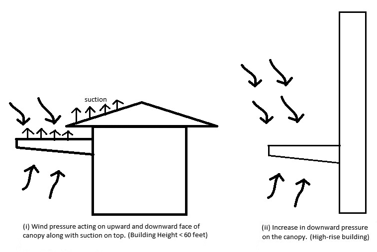
Figure 1. Differing wind pressures between short buildings and high-rise buildings.
A canopy is often suspended or supported by cables attached to the free end of the cantilever member of the canopy, as shown in Figure 2. The use of a cable system is preferable by architects because of its aesthetic appearance. However, it is a drawback because cables are not capable of resisting compression loads or moments, although they are suitable for resisting tension loads.

Figure 2. Illustration of a typical canopy connection to the wall.
Structural engineers generally prefer pipe systems in place of cable systems to mitigate some of these drawbacks. But in most cases, pipe sections are expensive to install and aesthetically not preferred. Instead of relying on a cable to resist the compression force, which it cannot, the canopy end connection to the parent wall is designed such that it resists the moment caused by the upward pressures as well as the downward pressures, as shown in Figure 3.
Parent Wall Design
Precautions must be taken such that the parent wall can resist the moment forces transmitted by the connection. The wall is often thin and may not be capable of resisting excess moments from the canopy connection reactions. Thus, additional vertical reinforcement can be provided near the tension face of the wall (generally at the inner face of the wall if the connection is made to the outer face or vice versa) to resist the tension caused by the moment acting on the wall, as shown in Figure 3. The reinforcement must be placed along with the typical wall vertical reinforcement before placing the wall. The length of the reinforcement provided must at least exceed the development length required.
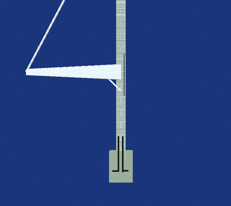
Figure 3. Illustration of the location where additional reinforcement is required.
As an alternate procedure, the moment due to the wind loads can be distributed over a length of the wall with the help of the stiffener plates or angles. The stiffener plates could transmit the forces from the moment couple over the length of the wall, thereby reducing the concentration of stresses over a small section.
Member Design
There is always a limit on the size of the canopy framing members. The main cantilever beams that resist the wind loads need to have sufficient size and thickness to resist the moment caused by wind loads. For this situation, a tapered cantilever beam with varying depth works very well. The cantilever depth can increase linearly from the free end of the member to the supported end, providing the required moment capacity.
Most canopies are mono-sloped; as such, the upward forces increase when the slope increases above 30 degrees. No significant increase in upward wind forces has been observed until the slope of the canopy reaches 30 degrees [Suárez, 2012]. If the canopy is situated at the corner of a building, more wind gets trapped underneath the surface of the canopy, thus exerting an upward pressure.
Foundation Design
The parent wall-to-foundation dowels must not only be designed for compression loads caused by the weight of the wall but also must be designed for tension loads, lateral loads, and over-turning moments caused by the canopy moment connection to the face of the wall. Also, the eccentricity of the embed plates, used for the canopy connection to the face of the wall, must be considered in the design of the foundation wall dowels.
Surface Cladding Design
Many canopy systems in buildings are now designed to accommodate glass cladding at the top surface. These glass cladding systems are extremely sensitive to the slightest deflections. These member deflections are often limited to a Span Length (in inches)/480 ratio (i.e., L/480). The glass panels are often subjected to both downward and upward pressures, which can create fatigue in the glass if not uniformly supported by the framing system members, resulting in localization of stresses.
The design of canopy framing members must consider deflections such that they will be within tolerable limits. Side sway deflections in the members caused by wind or seismic forces are often ignored by structural engineers but must be considered, especially when the cladding on the top of the canopy is glass.
Cable Design
A cable with an angle greater than 45 degrees with the horizontal provides the most favorable condition to resist the downward forces or tension forces caused by wind. Also, the connection at either end of the cable is always pinned.
Conclusions
It is important to understand code provisions for canopies, as engineers often underestimate the upper surface loads, overestimate the lower surface loads, and usually design for excessive uplift forces. Consideration of issues involved with pipe and cable support systems also are essential to adequate design.■
References
- Candelario Suárez, J. (2012). Wind-Induced Pressures on Canopies Attached to the Walls of Low-Rise Buildings. Masters. Concordia University.
- Roh, H., and Kim, H. (2011). Wind pressure distribution on canopies attached to tall buildings. Journal of Mechanical Science and Technology, 25(7), pp.1767-1774.
- Paluch, M., Loredo-Souza, A., and Blessmann, J. (2003). Wind loads on attached canopies and their effect on the pressure distribution over arch-roof industrial buildings. Journal of Wind Engineering and Industrial Aerodynamics, 91(8), pp.975-994.