
Seismic Design and Performance
While they meet the safety requirement of building codes, special reinforced masonry wall systems designed according to current codes and practice may not perform in the manner consistent with the design expectation in the event of a major earthquake. This stems from the fact that seismic design provisions focus primarily on strength and reinforcement details, without sufficient consideration of the actual behavior of a wall system under severe seismic actions. To have a consistent level of safety and performance, a performance-based design approach may be followed to ensure that the structural system performs predictably. This article summarizes some recent research findings that may help this design process.
Shear walls are the main seismic force-resisting elements in a reinforced masonry building. Depending on the aspect ratio, reinforcement details, and loading and boundary conditions, masonry shear walls can exhibit one of several, or a combination of, failure mechanisms when subjected to in-plane lateral loading. Slender cantilever walls are expected to have relatively ductile flexural behavior, while walls with a low shear-span ratio (Mu/(Vudv)) tend to exhibit brittle shear behavior dominated by diagonal cracking. However, walls with very low shear-span ratios can develop base sliding in lieu of diagonal cracking. The masonry building code, TMS 402-16 (TMS 2016), has provisions for evaluating the strength of a reinforced masonry wall governed by each of these mechanisms, and reinforcing requirements intended to prevent brittle behavior.
For high seismic regions (Seismic Design Category D or above), reinforced masonry walls must comply with the special wall requirements. These require the shear capacity design to prohibit brittle shear behavior and impose an upper limit on the amount of vertical reinforcement to ensure adequate flexural ductility if special boundary element requirements are not met. However, despite the requirements mentioned above, a special wall designed according to current codes may not necessarily develop flexure-dominated behavior. The wall may have failure governed by diagonal shear cracking when subjected to severe seismic actions. Perforated walls and walls in low-rise masonry buildings often have low shear-span ratios such that their flexural resistance is much higher than the shear strength. Such design is permitted by the code as long as the shear strength of the wall component is at least 2.5 times the shear demand, Vu. Hence, with the R factor equal to 5 and an expected overstrength factor of 2.5, the shear strength of a special load-bearing reinforced masonry shear wall so designed can be lower than the shear demand of the Maximum Considered Earthquake (MCE), which is 1.5 times the intensity of the design earthquake. In that situation, diagonal shear failure is likely to occur.
Another factor that makes reinforced masonry walls prone to developing shear-dominated behavior is the coupling effect of the horizontal diaphragms in a building. The coupling moments exerted by the horizontal diaphragms could significantly reduce the effective shear-span ratio of a wall. This effect is often under-estimated or neglected in masonry wall design primarily due to the lack of a reliable analytical method to capture the behavior of the diaphragms or the diaphragm-to-wall connections. As a result, the actual shear-span ratio of a wall could be significantly lower than what has been assumed in design. One justification for this design approach is that the absence of the coupling moments results in a lower lateral resistance of the walls, and ignoring these effects would, therefore, produce a more conservative design. However, this is true only if the resulting overstrength introduced by the diaphragm coupling is high enough to compensate for the reduction in wall ductility should the wall become shear dominated.
Despite the issues mentioned above, special reinforced masonry shear wall systems mostly meet the safety expectation of the codes according to recent studies (Stavridis et al. 2016; FEMA 2020). This can be attributed to the overstrength in a typical masonry building or the presence of other gravity load-carrying elements in the structural system, which can enhance the displacement capacity of the system by providing an alternative load path.
Masonry buildings often have significantly more structural walls than what is needed to resist seismic actions because of their dual function as architectural elements, such as exterior building envelopes and interior partitions. This is especially true for low-rise masonry buildings. The unintended coupling action of the horizontal diaphragms is another source of overstrength. This, however, depends on the out-of-plane bending stiffness of the diaphragms and the strength of the diaphragm-to-wall connectors. The study by Stavridis el al. (2016) has shown that a wall system with horizontal diaphragms constructed of precast hollow-core planks with cast-in-place concrete topping could have an overstrength factor of 4. The high shear strength of the walls was mainly attributed to the horizontal reinforcement required to satisfy the prescriptive requirement of the code for special walls.
Furthermore, studies have shown that a reinforced masonry building with shear-dominated walls can develop a displacement capacity substantially higher than what has been observed in quasi-static tests conducted on planar wall segments. This can be attributed to the presence of wall flanges or gravity frames, which can carry the additional gravity load after the webs of the walls have suffered severe shear failure, as discussed later in this article.
Performance Assessments
ASCE/SEI 41-17, Seismic Evaluation and Retrofit of Existing Buildings, the standard for assessing the seismic performance of existing buildings, considers multiple performance levels, and permits nonlinear analysis procedures. However, it has the same drawback as the design codes for new buildings by focusing on the performance of structural components rather than that of the system. In the standard, reinforced masonry walls are classified as either flexure controlled or shear controlled. For nonlinear static or dynamic analyses, it specifies modeling parameters to define the in-plane lateral force versus displacement backbone curves that represent the behavior of reinforced masonry wall components. The shape of the backbone curve and the maximum deformations permitted for a wall component depend on the expected failure mechanism, and for the flexure-controlled mechanism, on-the-wall aspect ratio, applied axial compression, and the total amount of reinforcement. Even though these curves are intended for assessing the performance of existing buildings, they may be adopted for the displacement-based design of new buildings or for evaluating the performance of a code-based design. Nevertheless, the nonlinear modeling parameters in the standard have not been updated for many years. Recent studies have shown that these parameters tend to substantially under-estimate the displacement capacity of a wall component or a wall system.
Based on quasi-static wall test data, Cheng and Shing (2018) have proposed a set of new modeling recommendations and parameters for reinforced masonry walls. The study has shown that wall cracking should be taken into consideration to estimate the elastic lateral stiffness of a wall. The value given by the theoretical formula recommended in ASCE/SEI 41-17 based on an uncracked section can significantly overestimate the stiffness observed in a wall test. Figure 1 compares the backbone curves constructed with the modeling parameters specified in ASCE/SEI 41-17, as well as those proposed in the study mentioned above, to the experimental data for a flexure-dominated planar wall and a shear-dominated one.
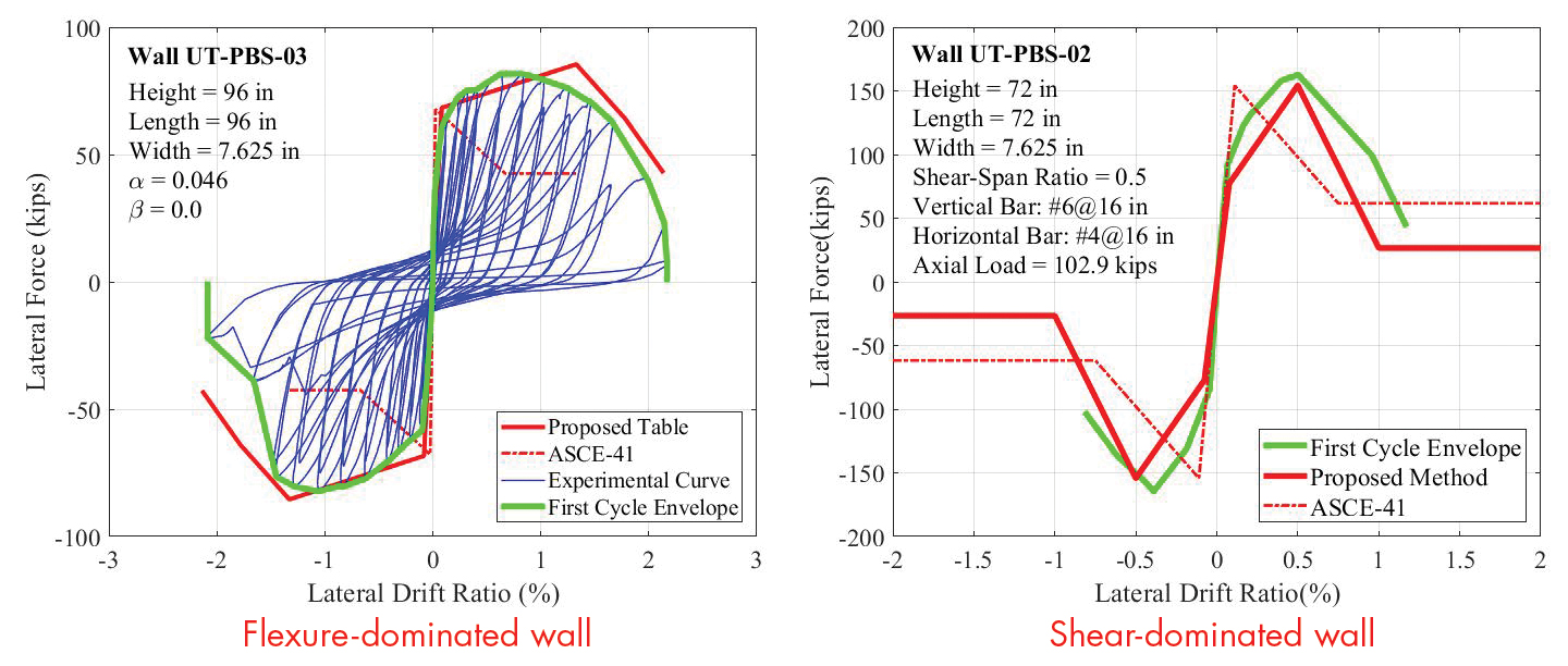
Figure 1. Comparison of nonlinear backbone curves constructed with ASCE 41 and new parameters proposed by Cheng
and Shing (2018) to experimental data.
While the proposed backbone curves provide a good correlation with the wall test data, a recent study discussed below has shown that they would still under-estimate the displacement capacity of a wall system by a considerable amount. Furthermore, it should be noted that, for the design of new reinforced masonry walls, the use of the stiffness formula proposed by Cheng and Shing (2018) could result in a substantial story-drift value that may not be practical with the stringent drift limits of ASCE/SEI 7-16, Minimum Design Loads for Buildings and Other Structures.
Seismic Performance
To investigate the displacement capacity of shear-dominated reinforced masonry wall systems and the influence of wall flanges and planar walls perpendicular to the direction of shaking (out-of-plane walls) on the seismic performance of a wall system, shake-table tests were conducted on two full-scale, single-story, fully grouted, reinforced masonry wall specimens to the verge of collapse. Each specimen had two T-walls as the seismic force-resisting elements and a stiff concrete roof diaphragm. The second specimen had six additional planar walls perpendicular to the direction of shaking. The design conformed to the special wall requirements of TMS 402-16. Each specimen was subjected to a sequence of earthquake ground motions with gradually increasing intensities. Specimen 2 on the shake table is shown in Figure 2a.
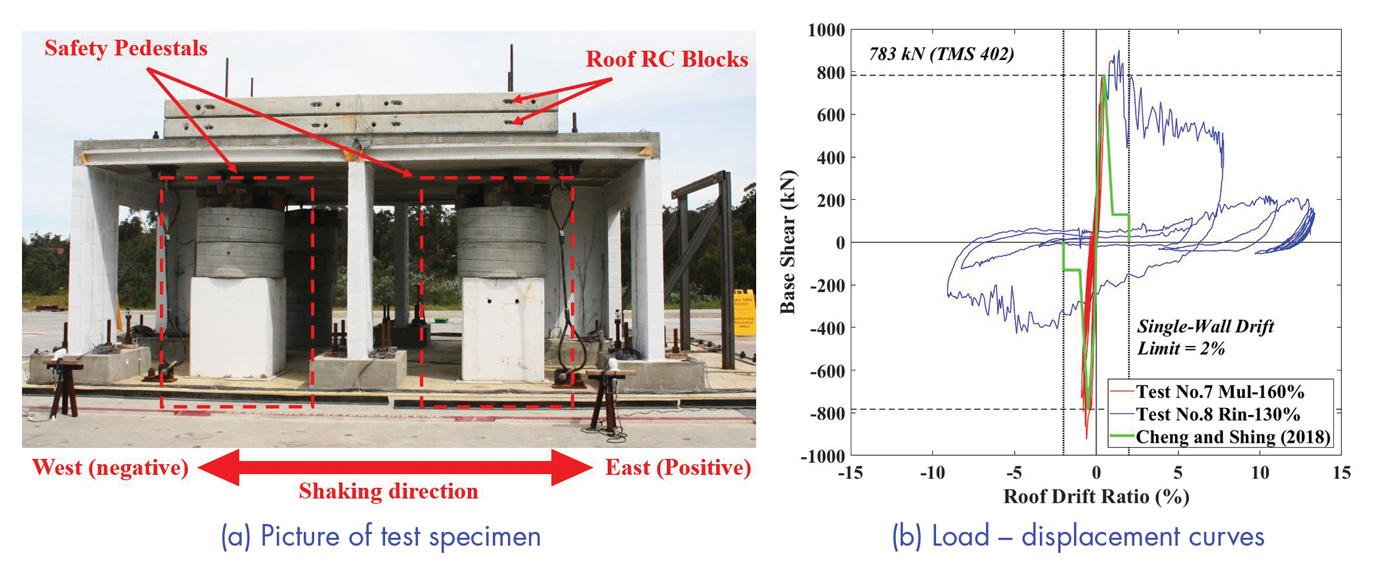
Figure 2. Reinforced masonry wall system (Specimen 2) tested on the outdoor shake table at the University of California, San Diego.
Figure 2b shows the base shear versus roof drift ratio curves obtained from the tests. The roof drift ratio is the roof displacement divided by the wall height of 235 mm (8 feet). The behavior of the T-walls was initially dominated by flexure; shear deformation became significant when the roof drift ratio reached 1%. Failure was eventually dominated by shear, as shown in Figure 3. The maximum roof drift ratio reached was 13.4%. The structure did not collapse. At the end of the tests, the webs of the T-walls had lost a significant amount of masonry due to spalling, and the residual roof drift was close to the maximum reached in the tests. At that stage, the roof weight was essentially carried by the wall flanges as well as the out-of-plane walls.
Figure 2b also shows the backbone curve constructed with the parameters recommended by Cheng and Shing (2018). In that calculation, it was assumed that the lateral resistance was provided by the T-walls only, and the shear strength of the T-walls was calculated with the formula given in TMS 402-16. The shear-span ratio (Mu/(Vudv)) of the T-walls was taken to be 0.86, assuming fixed-fixed end conditions because of the stiff roof diaphragm. It was assumed that the axial force in the T-walls was due to the gravity load only, with the axial force introduced by the horizontal load ignored. This is a reasonable assumption because the increase of the axial force in one wall due to the coupling effect of the roof diagonal is offset by a decrease in the other wall. It can be seen that the TMS formula provides a good estimate. Most importantly, it can be observed that the specimen exhibited a much higher displacement capacity and a gentler post-peak load degradation than the proposed backbone curve. Similar observations were obtained for Specimen 1.
The higher displacement capacity and gentler load degradation exhibited by the shake-table test specimens can be attributed to a couple of factors. One is the loading protocol. In quasi-static tests, wall segments were typically subjected to a large number of high-amplitude displacement cycles, which could be beyond what could have been experienced in an earthquake. The second is the presence of wall flanges and/or out-of-plane walls, which would carry the vertical load after the webs had been severely damaged in the tests. In quasi-static tests of planar wall segments, this alternative load path did not exist. However, it should be pointed out that the displacement capacity depends on the P-Δ effect of the gravity load as well as the residual lateral resistance of the walls.
Furthermore, it should be noted that the shake-table tests reported here had only uni-axial ground motions. In an earthquake, a building is subjected to forces in multiple axes. In that case, walls in different directions could suffer damage, and the displacement capacity of the structure would depend on the degree of damage in each direction. The damage would also depend on the presence or absence of gravity columns that could carry additional gravity load after the vertical load-carrying capacity of the walls has been depleted. Further shake-table tests are needed to investigate the effect of bi-axial horizontal ground motions. However, a recent numerical study using refined finite element models (Koutras 2019; FEMA 2020) has shown that reinforced masonry archetype buildings with shear-dominated walls and steel gravity frames could develop story drift ratios exceeding 10 to 15% without collapsing when subjected to bi-axial motions.
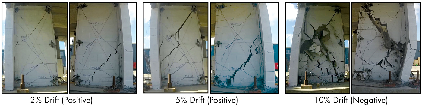
Figure 3. Damage in the T-walls of Specimen 2 at different roof drift levels.
Figure 3 shows the damage states of the T-walls in Specimen 2 when the roof drift level reached 2%, 5%, and 10%, respectively. The damage was relatively moderate and appeared to be easily repairable at a 2% roof drift. At 5% roof drift, the webs of the T-walls had widely opened diagonal cracks but without significant masonry spalling. At 10% roof drift, severe damage was incurred in the webs.
Recommendations for Design
A reinforced masonry wall system designed according to current code provisions could exhibit shear-dominated behavior in a significant seismic event. The displacement capacity and post-peak behavior of such a wall system depend on several factors, such as the presence or absence of wall flanges or gravity frames, the P-Δ effect of the gravity load, and the severity of wall damage induced in each of the two horizontal directions. If the flanges of the walls or walls in one direction have not been severely damaged or gravity frames are present in the building system, they can carry the additional gravity load when the webs of the walls have suffered severe diagonal shear failure. Such systems can sustain a much larger drift level than what has been observed from planar wall segment tests. However, damage to the walls can be severe when the story drift approaches 5% or more. To ensure safety and limit damage, it is essential to determine the potential failure mechanism and the associate drift capacity. The possibility of shear-dominated wall behavior can be checked by either elastic analysis or limit analysis with the consideration of the coupling moments of the horizontal diaphragms. If shear-dominated behavior is likely, sufficient shear reinforcement should be provided in the walls to control the opening of diagonal cracks and provide sufficient overstrength to limit the story drift to desired levels for both the design earthquake and the MCE. The sufficiency of the residual wall strength to counteract the P-Δ effect should also be considered. The Limit Design Method in Appendix C of TMS 402-16 may also be used to design and reinforce special walls whose strengths are limited by shear. However, the deformation limits imposed by this method are very low compared to the test data discussed above.■
References
ASCE (2016). Minimum Design Loads and Associated Criteria for Buildings and Other Structures (ASCE/SEI 7-16). American Society of Civil Engineers and Structural Engineering Institute, Reston, VA.
ASCE (2017). Seismic Evaluation and Retrofit of Existing Buildings (ASCE/SEI 41-17). American Society of Civil Engineers and Structural Engineering Institute, Reston, VA.
Cheng, J., and Shing, P.B. (2018). “Proposed update of nonlinear models for reinforced masonry shear walls in ASCE 41.” Proceedings of 11th National Conference on Earthquake Engineering, Los Angeles, CA.
Cheng, J., Koutras, A., and Shing, P.B. (2019). “A shake-table test investigating the drift capacity of reinforced masonry wall systems.” Proceedings of 13th North American Masonry, Salt Lake City, UT.
Ezzeldin, M., El-Dakhakhni, W., and Wiebe, L. (2018). “Reinforced masonry building seismic response models for ASCE/SEI-41.” Journal of Structural Engineering, 144(1).
FEMA (2020). Developing Solutions to the Short-Period Building Performance Paradox: Study of Reinforced Masonry Buildings. Federal Emergency Management Agency, Washington, DC.
Koutras, A. (2019). “Assessment of the seismic behavior of fully and partially grouted reinforced masonry structural systems through finite element analysis and shake-table testing.” Ph.D. Dissertation, University of California San Diego, La Jolla, CA.
Mavros, M., Ahmadi, F., Shing, P.B., Klingner, R.E., McLean, D., and Stavridis, A. (2016). “Shake-table tests of a full-scale two-story shear-dominated reinforced masonry wall structure.” Journal of Structural Engineering, 142(10).
NIST (2017). Recommended Modeling Parameters and Acceptance Criteria for Nonlinear Analysis in Support of Seismic Evaluation, Retrofit, and Design (NIST GCR 17-917-45). National Institute of Standards and Technology, Gaithersburg, MD.
Stavridis, A., Ahmadi, F., Mavros, M., Shing, P.B., Klingner, R.E., and McLean, D. (2016). “Shake-table tests of a full-scale three-story reinforced masonry shear wall structure.” Journal of Structural Engineering, 142(10).
TMS (2016). Building Code Requirements and Specifications for Masonry Structures (TMS 402/602-16). The Masonry Society, Longmont, CO.