
Part 3: Adaptive Reuse Feasibility Analysis
This four-part series (Part 1, STRUCTURE, November 2019, Part 2, January 2020) discusses how the collapse of a building during a demolition operation in Philadelphia in 2013, which resulted in several fatalities, led to the enactment of a City Ordinance to prevent similar calamities. As a result of the Ordinance, the author became involved with the structural investigation, review of the Site Safety Demolition Plan, and Demolition Special Inspections associated with the adaptive reuse of the Apex Hosiery Company Building located in Philadelphia.
South Side of Building
The typical two-way slab analyzed as a part of the investigation and feasibility study of the south side of the building involved the remaining east-west three-span structure and a typical north-south spanning slab of no more than five equal spans. Both slabs were analyzed using the Portland Cement Association (PCA) spSlab software. This software utilizes the Equivalent Frame Method (EFM) of analysis recognized by ACI. The EFM involves the representation of the three-dimensional slab system as a series of two-dimensional frames that are analyzed for the loads acting in the plane of the same frames.
The analysis was based on the conventional bottom and top reinforcing bar diameters and spacings documented as a part of the field assessment and yield strength of 40 ksi based on the laboratory test of two samples obtained from a slab that was scheduled to be demolished. Typically, the results of an analysis to determine the load-carrying capacity of an existing vintage reinforced concrete structure are greater than that which was specified by the original designer. This is because the ultimate strength method used for current day design and analysis typically provides greater capacities than that which would have been obtained via the working stress method of concrete design used in the 1920s.
However, using current-day methods of analysis, a superimposed service load capacity of only 120 psf was determined. This relatively low calculated capacity probably resulted because the method of analyzing two-way flat slabs in the early 20th Century was based on concepts that did not accurately represent the true behavior of this type of structure. Never the less, this capacity is consistent with the 1929 Philadelphia Building Code for light manufacturing buildings, as documented in the 18th Edition of Kidder Parker Builders’ Handbook. As a result, it was concluded that the Apex Hosiery Company’s utilization of the building did not involve heavy manufacturing that required a live load capacity of 200 psf per the same 1929 code.
The 120-psf uniform load capacity was input into the spSlab software as a 20-psf superimposed dead load and a 100-psf live load. This was based on the combined superimposed dead load of 15 psf for partitions (as required by the IBC) and 5 psf for miscellaneous suspended mechanical equipment. A superimposed dead load for ceilings was not included because there were no ceilings shown on the architect’s renovation drawings. The 100-psf live load was based on the IBC minimum requirement for residential public rooms and corridors, and the first-floor retail spaces located above the south side basement. The minimum IBC live load for the residential spaces on all floors of the building is only 40 psf.
A review of the structural drawings issued for the renovation project indicated that floor live loads used for the design were 40 psf, 100 psf, and 80 psf for Dwelling Units, Lobbies and Stairs, and Corridors, respectfully. Also, 15 psf was included as a partition allowance. All of these same design loads were less than or equal to the calculated 120-psf capacity of the existing two-way slab. Therefore, it was determined that the adaptive reuse of the existing remaining south side structure was feasible.
The investigation of the demolition equipment and debris loading conditions for the south side slab indicated that the existing distribution of top and bottom reinforcing in the east-west direction did not match the moment demand requirements of the spSlab software output. As a result, it was necessary to redistribute the negative moment provided by the software analysis to the positive moment region to justify the worst-case demolition equipment and debris loading conditions. The maximum negative to positive moment redistribution was limited to 20%, as allowed by Section 8.4 of ACI 318.
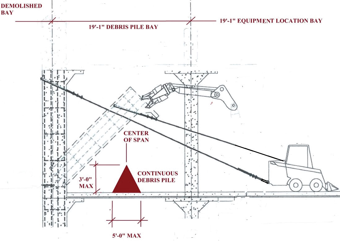
Figure 13. Analysis of demolition equipment and debris loading conditions revealed that proposed demolition equipment could be safely operated, but temporary storage of concrete debris was limited.
As a result of the analysis, it was determined that the proposed mechanized equipment could be safely operated inside the building during the demolition operation. However, the triangular volume of demolished concrete debris that could be temporarily stored in the span immediately adjacent to the span in which the equipment would be operating was determined to only include a maximum height of 3 feet and maximum width of 5 feet in the east-west direction in a continuous north-south mound, based on a unit debris weight of 120 pcf, as illustrated in Figure 13.
A lateral load analysis of the remaining existing building was not included as part of the assessment for the following reasons. The reduction in the height and footprint of the remaining building from its original configuration significantly reduced the sail area of the exterior vertical surfaces of the building. As a result, the lateral wind loads on the remaining building would be reduced considerably from that which it was assumed to have been initially designed for.
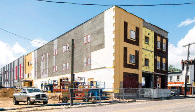
Figure 14. Lateral capacity of the post-renovation three-story building was assumed adequate based on the theory that the original six-story building sail area and mass translated to larger wind and seismic loads.
Therefore, because the lateral resisting capacity of the remaining three-story building seen in Figure 14 was more than likely designed for a greater accumulated wind load of the original six stories, it was reasonable to assume that the lateral load resisting capacity of the remaining structure was adequate. Also, although it is unlikely that the original designer of the structure analyzed the building for lateral earthquake loads, for this investigation, it was assumed that, similar to the wind loads, the current Code-based seismic base shear for the remaining three-story building was significantly less than the potential seismic loads on the original six-story building.
North Side of Building
The existing slab at the north side of the building was analyzed using the vintage method previously described for the SMI System, which was based on the early to mid-20th Century Working Stress method documented in the Taylor, Thompson, and Smulski textbook on Plain and Reinforced Concrete, Volume 1. The existing floor slab was analyzed as a 6-inch structural slab supporting a 1-inch-thick non-composite concrete topping. The flexural moment capacities for Unit B, in other words, the diagonal positive moment span, and Unit C, the negative moment at the column support, were established as a part of the analysis. The results of the analysis indicated that the slab system was capable of supporting a 120-psf superimposed uniform load similar to that established at the framed two-way slab at the south side of the building.
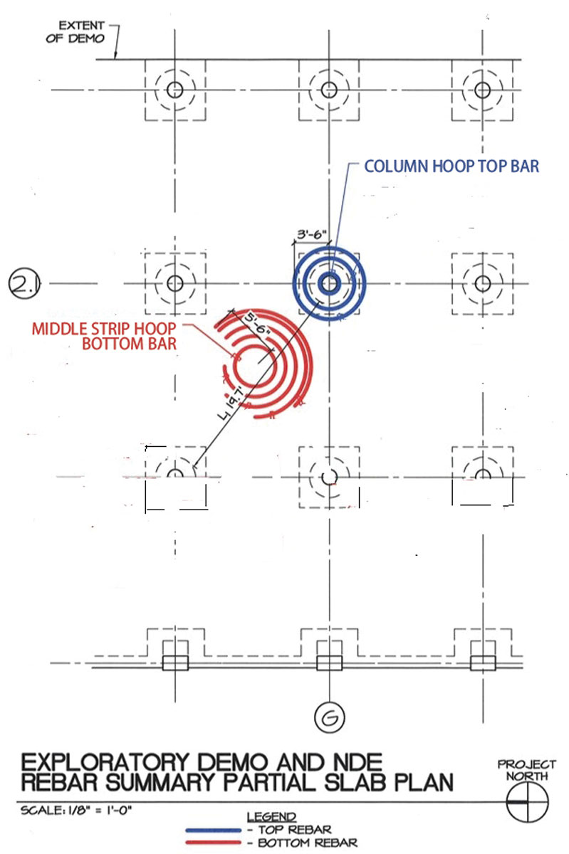
Figure 15. Analysis indicated that the north-side slab system could support a 120 psf superimposed uniform load similar to that established at the framed two-way slab on the building’s south side.
The results were based on the concept that the diagonal slab simple-spanned a distance of 3⁄5 of the clear span between the existing column capitals, and the slab, drop panel, and column capital cantilevered from the face of the column to support the end reaction of the Unit B diagonal span. The analysis was based on the bottom and top concentric reinforcing hoops documented as a part of the field assessment shown in Figure 15 and a yield strength of 27 ksi based on the laboratory test of one hoop sample shown in Figure 16 obtained from a slab that was scheduled to be demolished. An analysis of the SMI slab was also conducted for the same demolition equipment and debris loading conditions used for the south slab. The results of the analysis indicated that the northern SMI slab was capable of supporting the same demolition operations as the south slab.
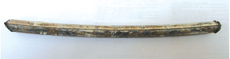
Figure 16. Feasibility analysis was based on top and bottom concentric reinforcing hoops with a 27 ksi yield strength resulting from a laboratory test of this sample.
As previously described, the SMI method of calculating positive moments is based on a simple span rather than continuous span condition, and negative moment is based on a cantilever condition around the circumference of the columns for the support of the surrounding reactions from the simple span slabs. This method of analysis was conducive to the proposed renovations because the interruption of the continuity of the existing slab as a result of the north-south line of demolition along the east face of the existing drop panels did not adversely impact the structural integrity of the remaining interior slab span that was converted to an end span condition.
However, because it was determined that a small portion of the top hoop reinforcing extended beyond the edge of the drop panel, it was necessary to extend the originally proposed line of demolition slightly further east, beyond the east edge of the drop panel, to avoid damaging the outer most top bar hoops. Adjusting the extent of the demolition was required because the flexural capacity of the existing SMI slab system is based on continuous, uninterrupted concentric rings of reinforcing bars, as required to resist the hoop stresses imposed by the deformation of the concrete slab. Therefore, all of the top hoops in the Unit C group had to be protected from damage or disruption of the surrounding concrete encasement.
A similar requirement to extend the east side of the line of demolition was also needed for the outer most hoops of the bottom bars located in the north-south span of the Unit A portion of the slab located along the line demolition. However, it was determined that the location of these same bottom hoops did not extend any further east than that documented for the top hoops over the drop panels.
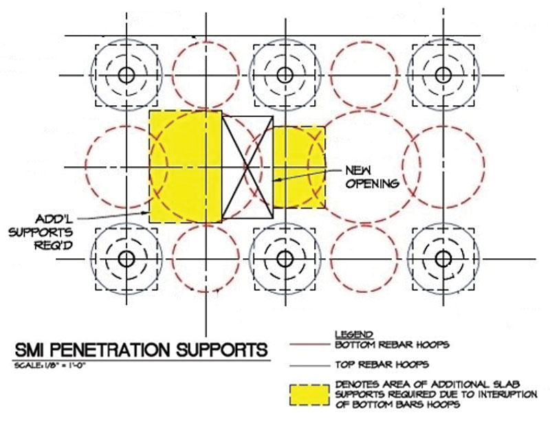
Figure 17. Interruption of SMI slab reinforcing hoops at new stair and elevator openings showing required additional slab supports.
For reasons similar to that described along the eastern edge of the demolition, interruption of the SMI slab reinforcing hoops at large openings associated with new stairs and elevators required additional slab supports beyond the new supplemental steel framing at the perimeter of the stair opening. This was also true for the new loadbearing CMU walls at the perimeter of the elevator opening shown on the renovation structural drawings. The approximate extent and location of the additional slab supports that were required at a typical large opening in the SMI slab was provided on a plan shown in Figure 17.
Conclusion
The results of the feasibility study for both the conventionally reinforced and SMI two-way slabs indicated the existing remaining structure was adequate for the proposed adaptive reuse with only a few minor modifications required at the edge of demolition and supports at new openings for the SMI slab. Part 4 of the series will include a discussion of the Demolition Special Inspections and the post-demolition assessment of the remaining structure.■