
A Comparison of Three Design Codes
Foundations for a building are required to support the structure so that it remains safe and functional, and so that they meet serviceability limits. Buildings with excessive cracking and movement (e.g. total settlement, differential settlement, tilt, etc.) are alarming and not acceptable.
When column loads are heavy, as in high-rise buildings for example, large piles or groups of piles are usually required to carry the loads down to a competent stratum. Bored piles, also referred to as auger-cast piles, are large-diameter, cast-in-place concrete piles, usually lightly reinforced by steel reinforcing bars (0.5%) under gravity loads. Circular boreholes are drilled in the ground before placing concrete into the borehole. The reinforcing steel can be set in the holes before the concrete is placed or “wet-set” before the concrete is allowed to set. Common bored-pile sizes range from 30 inches to 60 inches (750 mm to 1,500mm) in increments of 4 inches (100mm).
This article compares the structural capacity calculation of bored piles in compression using three design codes: ACI-318, Building Code Requirements for Structural Concrete and Commentary; the Eurocode (EC2); and CP4:2003 (Singapore CP4).
Design Codes
There are generally two types of design methods: allowable stress design (ASD) and load and resistance factor design (LRFD). In many parts of the world, ASD and LRFD are known as working stress (permissible stress) design and limit-state design, respectively. ASD compares capacities derived from the allowable stress (factored down from ultimate) against the service loads without any load factors, while limit-state design has factors for loadings and partial factors for materials (Table 1).
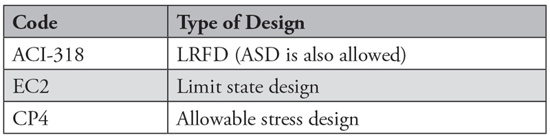
Table 1. Codes and design method.
In the design of piles, both the geotechnical (soil strength) capacity and structural (material strength) capacity must be checked. For an economical design, the structural capacity and geotechnical capacity should be as close as possible.
Geotechnical Design
The geotechnical capacity of piles can be calculated based on site investigation data. For piles founded in soil, unit shaft friction and end-bearing are summarized in Table 2.

Table 2. Unit shaft friction and end bearing.
In some parts of the world, where there is prior pile design experience in similar ground conditions, it is possible to correlate the shaft friction and end-bearing to standard penetration test (SPT) N values. For example, bored piles in a specific locality may have the values shown in Table 3. (Example: A soil with SPT value of 100 may have unit shaft friction of 3×100 = 300 kPa = 44 psi)

Table 3. Example of shaft friction and end bearing based on SPT.
In design, it is often prudent to impose an upper bound on shaft friction and end-bearing as a safety precaution to avoid using values that are not achievable or come with excessive settlement.
Designers need to recognize that end-bearing requires much more pile settlement to mobilize as compared to shaft friction. The condition of the pile toe is difficult to ascertain. For these reasons, designers may want to exercise extra caution when selecting end bearing values in design. Codes typically impose a higher factor of safety for end-bearing as compared to shaft friction.
The different partial safety factors applied to the calculated shaft friction and end bearing may also depend on conditions such as whether load tests were carried out and the type of loading (compression or tension).
To illustrate, Table 4 shows the different factors used in the different codes.
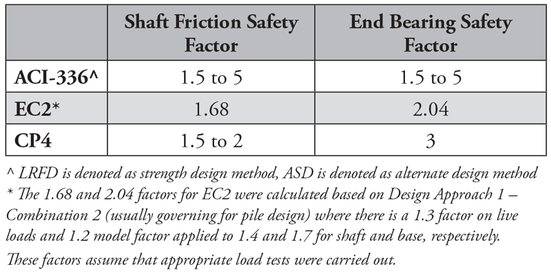
Table 4. Partial factors on shaft friction and end bearing.
Designers need to be mindful of the different factors that are required on shaft friction and end bearing, and the appropriate corresponding factors to be applied to the loadings, depending on the code and type of design adopted.
Due to the uncertainties of pile design and construction, load tests are desirable to verify that piles can meet settlement criteria under the design loads. For example, the governing code may specify that, when a test pile is loaded to 1.5 times the unfactored column load, the pile settlement should not exceed 0.6 inches (15 mm) (from CP4).
Structural Design
Bored piles are usually designed to carry compression loads, similar to columns in a building. The main difference is that columns are cast above the ground while piles are cast underground. Other differences are summarized in Table 5. Because of these differences, the structural capacity of a pile determined from code equations usually is lower than column capacity of a similar size and reinforcement.
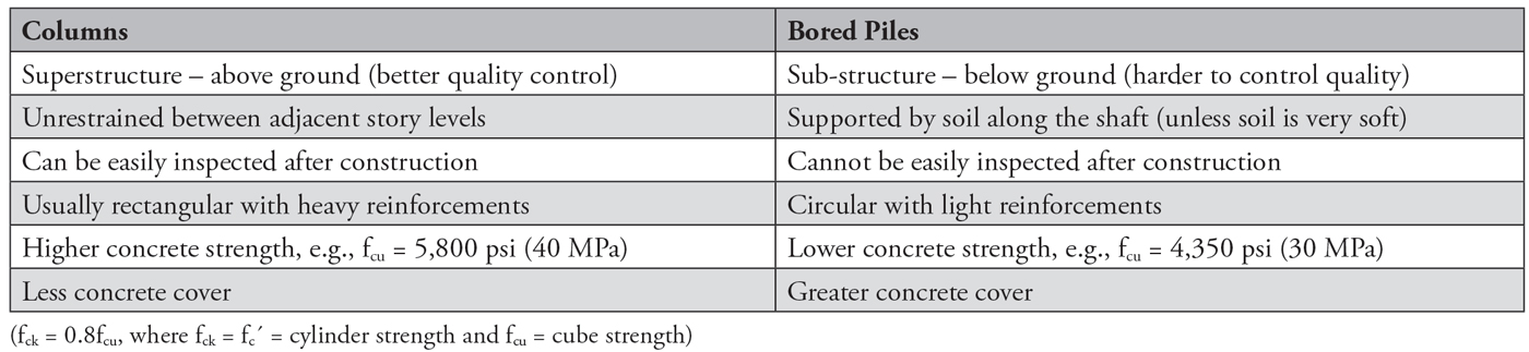
Table 5. Difference between a column and a bored pile.
Under gravity loads, bored piles in compression can be nominally reinforced (using minimum reinforcement). Usually, it is more economical to use a larger pile with nominal reinforcements compared to a smaller pile that is heavily reinforced. However, smaller diameter piles with heavier reinforcements may be adopted in certain situations such as space constraints or low headroom. For comparison in this article, only nominally reinforced bored piles founded in soil are discussed.
Structural Capacity Based on ACI-318
In the U.S., ACI-318 is a commonly used standard for the design of reinforced concrete structures. ACI-318 is primarily an LRFD code, but ASD is also allowed. Bored piles are known as drilled shafts, drilled piers, or auger-cast piles. The structural design of drilled piers is similar to a beam-column. However, in most practical cases, the design can be simplified to a short column by assuming the bending moment is negligible (gravity loads only) and the pier is laterally restrained, unless in the case of very soft soil (for example, less than 1.5 psi (10 kPa) shear strength). U.S. practice also includes seismic considerations in certain areas, which may require special detailing requirements, such as spiral hoops (for added shear strength) and more stringent reinforcement spacing and limits. For column design, ACI-318 provides the following well-established equation for column capacity:
φPn = φ(0.85f´cAc + fyAst)
ACI’s strength reduction factor, φ, is an overall factor to reduce nominal strength, similar to the partial safety factor for materials in the Eurocodes (e.g., 1.5 for concrete).
A strength reduction factor, φ, of 0.75 is used for spirally reinforced columns and 0.65 for tied columns. There is a further reduction factor of 0.85 and 0.8 for spiral and tied columns, respectively, to account for eccentricities.
Ignoring the contribution of steel (for a nominally reinforced pile), the ultimate capacity for a tied column is:
φPn = (0.65)(0.8)(0.85)fckAc = 0.442 fckAc = 0.35 fcuAc
This gives a working load of 0.25fcuAc after dividing by a combined load factor of 1.4.
Note that ACI-336.3R for drilled piers specifies load factors of 1.4 and 1.7 for dead load and live load, respectively, whereas ACI-318 specifies load factors of 1.2 and 1.6. The difference in load factors for drilled piers and columns suggest that underground concrete is more uncertain and requires a higher factor of safety compared to concrete columns in a superstructure.
The U.S. model building code is the International Building Code (IBC). In IBC (allowable stress design), the allowable stress in concrete is 0.33f´c (0.26fcu). This is in line with a general rule of thumb that design stress is a third of material strength for piling.
Structural Capacity Based on CP4
For rock-socketed piles with full-length reinforcement, using a short column formula, CP4 states that the ultimate structural capacity is given by the sum of stress multiplied by area for both concrete and steel components:
Pu = 0.4fcuAc + 0.75fyAs
where fcu and fy are concrete and steel strength, respectively, and A is area. To derive the working load, using a minimum safety factor of two, the equation becomes:
Pu = 0.2fcuAc + 0.375fyAs
In CP4, structural capacity (working stress) of nominally reinforced bored piles is calculated using 0.25fcu (ultimate cube strength) but limited to a maximum of 1,088 psi (7.5 MPa). Some engineers are tempted to view 0.25 as a “safety factor” for structural capacity using a permissible stress perspective, giving a false sense of safety. However, this is not strictly correct because the 0.25 is a value obtained after accounting for several aspects of cube strength which are different compared to actual concrete cast-in piles.
The derivation of 0.25 was strongly influenced by BS8110 (or local Singapore CP65), which was the corresponding reinforced concrete design code used in conjunction with CP4. When a column is loaded to failure in compression, the ultimate capacity is the sum of concrete and steel components, and it is given by an empirical formula:
N = 0.67fcuAc + fyAs (Note that 0.67fcu = 0.85fck, using fck = 0.8fcu)
where fck = f´c = cylinder strength and fcu = cube strength.
This is the maximum load, independent of creep and shrinkage effects. The 0.67 factor applied to cube compression strength of concrete is to account for differences such as size (actual structural element is much larger than cube), boundary conditions (actual building load on column versus loading using compression testing machine), rate of loading (much faster rate in cube test), and quality of compaction (cube test is properly compacted).
An additional “partial safety factor” of 1.5 needs to be applied for design against ultimate collapse (note that this factor is not meant to bring it down to working load capacity). Because bored piles are lightly reinforced, the contribution from steel can be ignored. This means the ultimate pile structural capacity reduces to:
N = 0.45fcuAc
The coefficient 0.45 is further reduced by 10% to 0.4 to account for eccentricity and tolerances in construction. To bring the ultimate capacity to working load capacity, 0.4 is divided by 1.5 (equivalent to a combined load factor) to obtain a coefficient of 0.267 (note: 1.4 and 1.6 were load factors for dead and live load, respectively, based on British Standards). Therefore, CP4 recommended the pile structural capacity (working stress) to be 0.25fcu. This capacity is to be compared to column loads (serviceability limit state) acting on the pile, without any load factors.
When CP4 was in use, the common concrete strength for bored piles was C30 (fcu = 4,350 psi or 30MPa), which means that the allowable stress was 1,088 psi (7.5 MPa). Also, CP4 limits concrete strength to 1,088 psi (7.5 MPa) to account for quality control issues when pouring concrete into a hole underground. Even with higher concrete strengths, there is a need to be mindful that such a high strength of concrete may not be adequately compacted and subjected to issues associated with bored pile construction, such as mixing with water and soil, necking, etc. For this reason, 1,088 psi (7.5 MPa) was the maximum working stress allowed in concrete, even if much higher strength of concrete was used.
Structural Capacity Based on EC2
Using Eurocodes, the structural design of reinforced concrete is in accordance with EC2. EC2 provides the following equation for predicting the ultimate capacity of reinforced concrete piles:
NRd,p = Acfcd,p where fcd,p = αcc,p fck/γc,f
According to EC2, αcc “is the coefficient taking account of long-term effects on the compressive strength and of unfavorable effects resulting from the way the load is applied” and 0.85. γc,f is the partial safety factor for concrete (1.5 x 1.1; 1.1 being required for casting piles without a permanent casing).
With all these factors, the ultimate stress in concrete becomes:
fcd,p = αcc,pfck/γc,f = 0.85 x (0.8fcu)/(1.5×1.1) = 0.412fcu
Under Eurocodes, the load factors for permanent (dead load) and variable action (live load) are 1.35 and 1.5, respectively. Because permanent loads are much higher than variable loads for most structures, a combined load factor can be assumed to be approximately 1.4.
The working stress of concrete then becomes 0.29fcu (higher than 0.25fcu using ACI-318 or 0.25fcu using CP4).
By comparing the working stress allowed for concrete, it appears that EC2 allowed a 16% higher value as compared to ACI-318 and CP4. However, in EC2, it is necessary to reduce the design diameter of a bored pile by 2 inches (50mm) for diameters greater than or equal to 40 inches (1,000mm) when there is no permanent casing. This design diameter reduction is on top of the 1.1 factor applied to the concrete partial factor of 1.5. Such a reduction in capacity using EC2 equations is to allow for greater uncertainties in casting concrete underground without a permanent casing. With these two explicit provisions addressing uncertainties in the construction process, EC2 uses a slightly higher allowable concrete stress of 0.29fcu. If the 2-inch (50mm) reduction in design diameter is accounted for, the concrete stress in EC2 reduces by another 10% (using 382/402 = 0.9) to 0.26fcu.
Construction Tolerances
Column loads are usually transferred to bored piles through a pile cap. Pile caps help to distribute loads to piles in a group and minimize the effects of eccentricity, that is, variation in the individual pile positions. Pile caps may need to be redesigned if there are piles constructed exceeding the allowable tolerances. Construction tolerances allowed by the codes are summarized in Table 6.

Table 6. Construction tolerances for bored piles.
Conclusion
Although there is no upper limit on concrete stress in ACI-318 and EC2, designers may not want to use the maximum stress allowed. For example, a concrete with fcu = 5,800 psi (40 MPa) has allowable stress of 1,711 psi (11.8 MPa) designed with EC2. In practice, the designer may choose to limit the stress to 1,450 psi (10 MPa) as an additional safety precaution.

Table 7. Allowable concrete stress in bored piles in compression.
Allowable compressive stress in concrete for bored piles appears to be consistent across the three different codes (Table 7). Most codes recognize that concrete cast underground is more uncertain compared to a column cast in a superstructure and, therefore, a safety factor that accounts for this is required. CP4 uses a 1,088 psi (7.5 MPa) stress limit to guard against quality issues and therefore places a disincentive for using higher strength concrete, while the other codes do not prescribe concrete strength limits. Designers can take full advantage of the higher concrete stress and specify higher strength concrete for bored piles. However, designers should be cautioned on the need to ensure stringent quality control measures during pile construction and verify that concrete strength can be achieved on-site.■
References
ACI 318-14, Building Code Requirements for Structural Concrete and Commentary, 2nd printing. Farmington Hills, MI: American Concrete Institute, 2014.
ACI-336.3R-93, Design and construction of drilled piers, Farmington Hills, MI: American Concrete Institute, 2014.
SS CP4:2003, Code of practice for foundation, Singapore Standard, SPRING Singapore, 2 Bukit Merah Central, Singapore 159835.
EN 1992-1-1:2004, Design of concrete structures – General rules and rules for buildings, European Committee for Standardization, rue de Stassart, 36 B-1050 Brussels.
EN 1997-1, Geotechnical design – General rules, European Committee for Standardization, rue de Stassart, 36 B-1050 Brussels.
EN 1536:2010, Execution of special geotechnical works – Bored piles, European Committee for Standardization, rue de Stassart, 36 B-1050 Brussels.