
A new timber truss pedestrian bridge in Oregon is using high-capacity timber connections. The span is 114 feet with a truss height and width of 16 feet between centerlines of chords. Historically, timber truss bridges have light roof structures when compared to the timber truss and deck structure. The roof for this bridge weighs more than the truss and deck structure. This provided unique challenges in a high seismic region. Bottom chord seismic tension loads are approximately 300 kips and typical knife plate connections could not develop the strength required for the bottom chords. The recent introduction of proprietary connections utilizing multiple internal steel plates and screws provided a challenge for a much larger connection.
The initial bottom chord size from the architect was proposed as 14×18 visually graded sawn timber. When analyzing typical external connection plates with bolts, the connection became so long that the group action factor, based on the National Design Specification® (NDS®) for Wood Construction, became too large, even when looking at various bolt diameters, spacing, and larger chords. The author proposed a continuous glulam member to avoid the tension connections, but that was not the aesthetic the architect wanted for this bridge. Once there was an agreement to use multiple internal knife plates, a design that almost met the tensile capacity of the chord member itself was sought. The upper design strength of the connection is the allowable tensile capacity of the individual wood segments between knife plates, so removal of wood for the knife plates would never allow for the full allowable tensile capacity of the chord away from the connection. After analysis, truss bottom chords were required to be 18×18 Douglas Fir-Larch (DF-L) Select Structural, with a non-incised pressure preservative treatment.
Physical Properties of Timbers
The following discussion explains some of the issues related to the physical properties of timbers and how they impact the design process. For a project such as this, buying an 18- x 18-inch timber off the shelf is not customary. The author’s firm, Stonewood Structural Engineers, worked directly with the contractor and lumber broker to source the timber and a mill which has on-site graders to get the right timber to meet the specifications.
The green milled size of this timber would be 17½ inches square based on the manufacturing and grading rules. Minimizing movement after the CNC processing of the timber is essential for proper fit-up, so Kiln Dried (KD) timber was specified. The Moisture Content (MC) can vary significantly throughout the depth of the timber. At the time a DF-L tree is felled, the MC is about 37% for the heart-wood (center-of-tree) and about 115% for the Sapwood (outer surface) although it dries out much faster than the heart-wood. The KD process is an art form to get a dry timber while minimizing checking and avoiding “killing” the timber and making it brittle, so choosing an experienced kiln operator is important. When specifying MC19 (19% moisture content) KD timber, the moisture content is typically measured with a standard prong moisture meter which may have prongs less than 3⁄8-inch-long (Figure 1). With this approach, there is no guarantee that the MC deeper below the surface is even close to MC19. The measurement was specified to be taken 3 inches below the surface (Figure 2) to have a better chance of having an average MC19 throughout the wood.
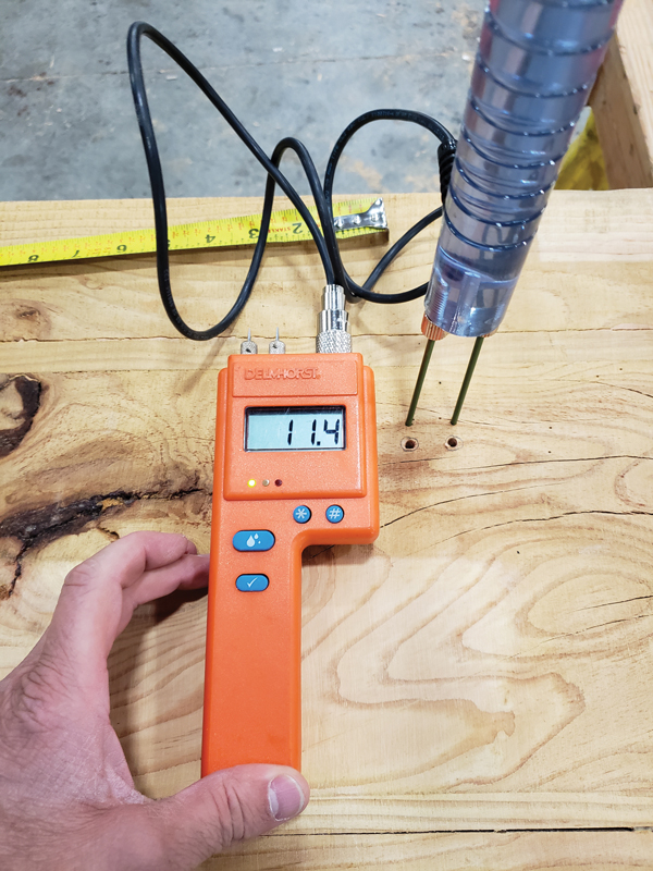
Figure 1. Initial moisture content with standard prong.
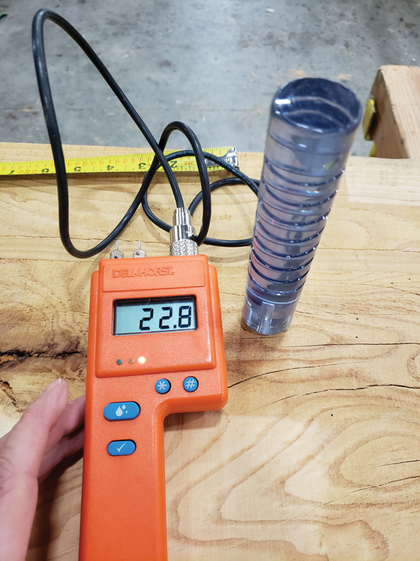
Figure 2. Initial moisture content 3 inches below surface.
When a timber is milled at MC19, versus green, the final dressed size requirement is different. The MC19 minimum dressed size is 17×17 inches versus 17½ x 17½ inches when milled green. The mill started to plane the timber at the smaller dry dimensions once the timber was removed from the kiln. The moisture content was found to be closer to 25% moisture content at 3 inches below the surface. Milling was stopped at that point. The kiln operators felt that additional time in the kiln to lower the moisture content further would create excessive checking, yet the members did not meet the criteria for milling at the 17- x 17-inch criteria. A rule of thumb is a 1%-dimensional change for every 4% change in moisture content to determine the acceptable dressed size. Due to the higher moisture content, it was determined that the final milled size needed to be 17 3⁄16 x 17 3⁄16 inches. For member design, the full 17½-inch dimension is used (grade rules account for this) and, for connection design, the 17-inch dimension is used. The equilibrium moisture content (EMC) for the location of the bridge ranges from about 12% to 17% throughout the year.
Right before fabrication of the timber was scheduled to begin, the project was delayed. This allowed Stonewood to cut two sections of timber off the mock-up to determine the actual moisture content of the timber, instead of a single measured point 3 inches below the surface. Over two months, the timber block, which initially measured 17 x 17 x 12 inches and weighed 77.6 pounds (38.8 pcf), went into the author’s oven at home at 170 degrees Fahrenheit. It underwent about 22 cycles of about 12-18 hours before reaching an oven-dry weight of 62.0 pounds (31 pcf). The initial moisture content is determined by the formula MC = (initial weight – oven dry weight)/oven dry weight. For our sample, this equates to 25.2% moisture content. As a reference, the initial surface moisture content with a standard prong was 11.4% (Figure 1) and at 3 inches below the surface was 22.8% (Figure 2). Our initial direction to measure moisture content at 3 inches below the surface slightly underestimated the actual moisture content of the timber.
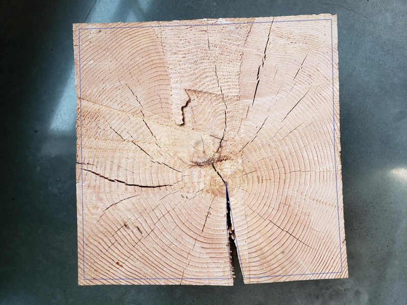
Figure 3. Blue outline of smaller oven-dry timber over initial timber.
Additionally, from the initial moisture content of 25.2% to the oven-dry condition, the timber shrank on average from 17 inches to 16¼ inches. The diagonal dimension shrank from 23 7⁄8 inches to 23 3⁄8 inches. The timber shrank relatively less across the diagonal when compared to the face dimensions. This created the slightly cupped faces that can be seen in Figure 3. The actual face dimensions shrank down to 16¼ inches, where the rule of thumb of 1%-dimensional change for each 4% MC change predicts a 15.9-inch oven-dry face dimension. This is likely due in part to a comment from the kiln drying representative, made before the kiln drying started, that large square timbers similar to what Stonewood was using will often shrink less than timbers that are more rectilinear, due to three-dimensional restraint that occurs.
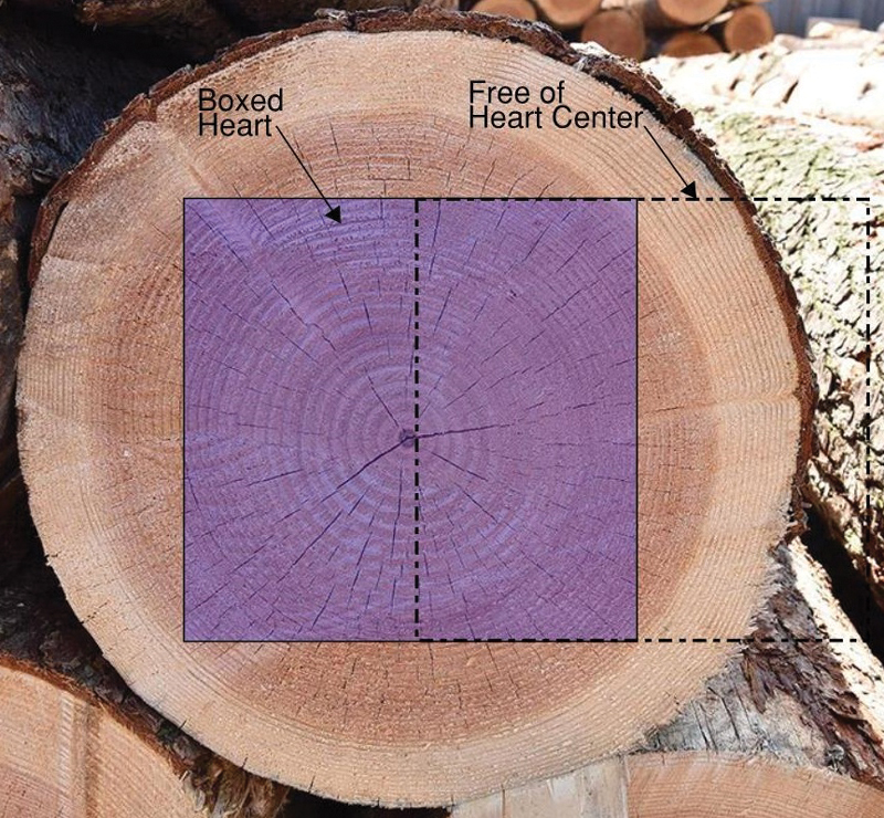
Figure 4. Boxed heart manufacturing yields smaller checks and allows for better utilization of the tree.
Boxed heart timber was used because it allows for better utilization of the tree and requires a smaller (less expensive) tree. It can also yield smaller checks which are more evenly spread around the perimeter, where Free of Heart Center (FOHC) will have one face of the timber that is cut close to the heart, which is where many larger checks originate. For 18×18 Boxed Heart, a 30-inch-diameter log may be required, and for 18×18 FOHC, a 50-inch-diameter log may be required (Figure 4).
Timber Specification and Detailing Process
- Order 50% more timber than required to be able to choose the correct grade, appearance, and check locations at critical connection zones.
- Mill oversized in its green state.
- Kiln dry until MC19 measured at 3 inches below the surface.
- Select timbers and mill rough sawn section with true 17-x17-inch-square dimensions, or larger size based on actual moisture content higher than MC19.
- CNC all cuts and bolt holes per final connection design (discussed in the Multiple Internal Plate Connection Design Issues Section).
- Apply pressure preservative treatment so that it penetrates all end grain, cuts, and holes.
Multiple Internal Plate Connection Design Issues
The NDS has a lower bound connection design approach in section 12.3.9. The method of checking the bolt-wood yield mode capacity at each shear plane, as outlined in this article, rather than using NDS 12.3.9, is a rational method which is allowed in the code but can be challenging to shepherd through the plan review process depending on the jurisdiction and its familiarity with wood design. Also note that values for drift pins have a 25% reduction in the NDS due to the lack of heads, nuts, and washers. The choice of connection plate numbers and locations is critical to the design. Figure 5a shows the standard internal knife plate. This is the typical approach for a hidden connection. Based on a preliminary NDS yield limit analysis, the 4-inch dimensions, noted as x(IIIs), at the exterior wood segments, represent the minimum width required to force yield mode IV and not allow a smaller mode IIIs capacity. The double crosshatch represents the region of excess wood not being utilized for the dowel capacity.
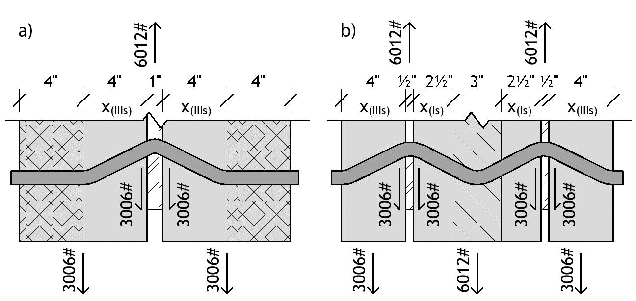
Figure 5. a) Standard internal steel knife plate; b) Multiple steel knife plates.
Figure 5b shows how the use of multiple knife plates doubles the capacity of each dowel in the connection. The 2½-inch dimensions, noted as x(Is), represent the minimum width required to force yield mode IV and not allow a smaller mode Is capacity. The single cross hatch represents the area not required to maximize the dowel capacity, but which is required to preclude a net tension failure of the inner section, as explained below. As noted above, each shear plane was analyzed to determine bolt capacities. For a multiple interior knife plate connection, the assumption is that Modes II, IIIs, and IIIm cannot occur at the inner sections, and Modes II and IIIm cannot occur in the outer sections. The spacing between knife plates is important when determining the capacity of the dowel, but of more importance is the impact the spacing of the plates has on the net wood tension failure mode and wood tear-out failure modes that must be checked at all connections (NDS Appendix E provides an approach for this). The net tension failure mode is shown in Figure 6. The inner section between plates resists about twice the load as the outer sections, as can be seen at the bottom of Figure 5b. Therefore, as a first design step, set the inner section as twice the width of the outer sections.
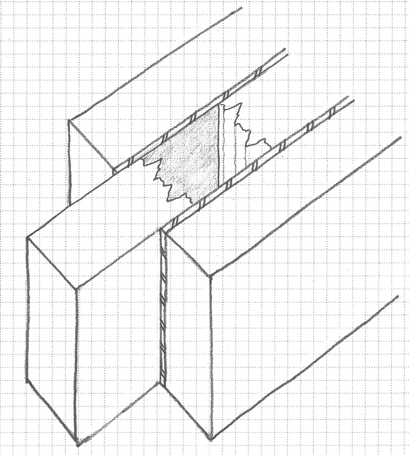
Figure 6. Net section tension failure mode.
Table 1 shows the comparison of adjusted bolt capacities and net section capacities for a double 3⁄8-inch knife plate connection with (4) rows of (7) 7⁄8-inch-diameter bolts (28 total). The author chose to show bolt capacities in this table instead of the reduced drift pin capacities because the higher bolt capacities create more “net tension” and “tear-out” controlled designs, where the reduced drift pin capacities controlled the design except where the inner members’ thickness was 6 inches or less.
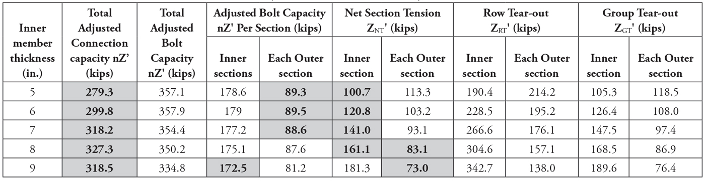
Table 1. Comparison of adjusted bolt capacities and net section capacities for the double 3/8-inch knife plate connection with (4) rows of (7) 7/8-inch-diameter bolts (28 total).
The final connection shown in Figure 7 utilized the 8-inch inner section and (4) rows of (8) 7⁄8-inch diameter drift pins. Table 2 shows the final design capacity of this connection. Note that this drift pin connection has 10% less capacity even though it has (4) more dowels, because of the 25% reduction for drift pins.
Table 2. Comparison of adjusted drift pin capacities and net section capacities for the double 3/8-inch knife plate connection with (4) rows of (8) 7/8-inch-diameter drift pins (32 total) used on bridge bottom chord splice.
Connection Design Steps
1) Determine dowel diameter and number of knife plates that maximize the wood section use for yield mode IV dowel capacity. 2) Determine yield mode capacity at each bolt shear plane. 3) Determine load in each wood section based on the number of shear planes and capacities in step two above. 4) Check net tension, group tear-out, and row tear-out. 5) Modify variables to eliminate failure modes and/or optimize the connection. 6) Check steel plate capacities per appropriate steel standards.
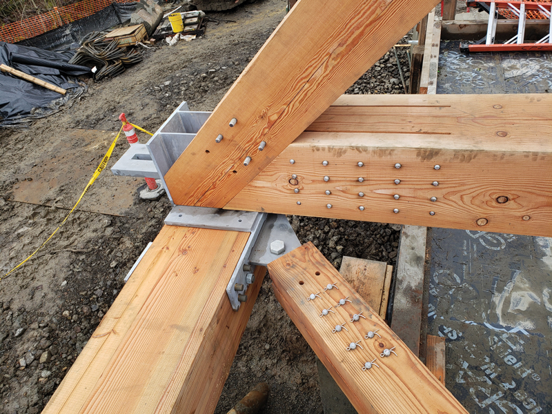
Figure 7. Final connection in progress at concrete abutment not yet placed.
Technical Topics
Note that the lower bound approach in NDS 12.3.9 can be unconservative for this specific type of connection design. When proportioning the spacing of members and knife plates, group tear-out and net tension failure of the members in the connection area is a critical factor. If member size or knife plate spacing is based on a lower bound value per 12.3.9 when the more rigorous calculation anticipates a higher capacity, a potential group tear-out or net tension failure mechanism could be forced in a connection.
One more lesson learned on this project was that compressive member end bearing requires a 20 gauge or thicker bearing plate. Without this plate, the NDS requires a 25% reduction in bearing capacity. This affected the end-to-end bearing capacity of truss top chord members.
Fabrication Adjustments
Figure 8 shows the mockup of the typical bottom chord connection with only 28 pins on each side. Four more pins were added to each side on the structural detail to account for the drift pin reduction. The 7⁄8-inch dowels were installed flush and proud of the chord face. As a result of the mockup, dowels were lengthened to extend 3⁄8 inches proud of each face, knife plate slots were reduced to be 1⁄16 inch over steel plate width, and sections of wood marked 1-4 were removed for oven-dry moisture testing and measurement of shrinkage. Because the mockup moisture content was higher than specified, more vertical short slotted holes were used in the steel plates and the milled size was increased from 17 inches square to 17 3⁄16 inches square. Note that, for the two blocks of wood cut for drying, the 17-x17-x12-inch section fit into the home oven with ¼ inch to spare, and the drying process made the house smell great.
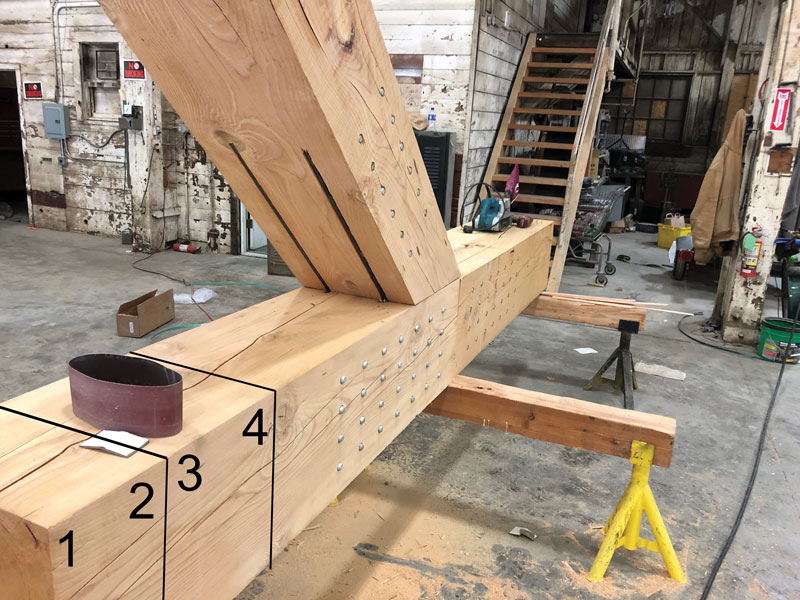
Figure 8. Mockup of the typical bottom chord connection, which led to fabrication adjustments.
Summary
An 18-x18-inch timber was designed as the bottom chord of a bridge truss. For the truss tension splice connection, choosing the optimal number of interior knife plates, and determining a dowel diameter that most effectively utilized the entire width of the timber, allowed for higher capacity and more compact connections.■