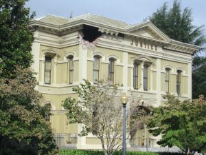
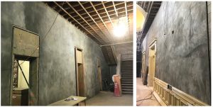
On August 24, 2014, the South Napa Earthquake left the Napa County Historic Courthouse heavily damaged with partially collapsed walls, ceilings, and extensive wall cracking (Figure 1). The City of Napa red-tagged the courthouse as unoccupiable, which began the extensive damage documentation and repair effort. The overarching goal throughout this process was to provide a solution to repair and preserve as much of the historic building as practical while providing improved detailing.
The historic courthouse building is a 140-year-old, two-story, unreinforced brick bearing wall structure with wood-framed floors and roof, located in downtown Napa. The building had a significant remodel and retrofit in 1977 which included concrete frames for new openings, concrete or concrete masonry unit (CMU) infill of existing openings, and many other small renovations.
The observed earthquake damage in the brick walls varied from miscellaneous small cracks to significant cracking with permanent in-plane and out-of-plane displacements in both principal directions, to the partial collapse of wall sections. The repair approach needed to provide a similarly diverse set of options to match observed conditions. Traditional brick repair methodologies, repointing, and grout injection were used in areas of minor damage where appropriate. Complete wall reconstruction using specially detailed CMU was used in areas with permanent deflections and partial collapse. However, a third repair approach was needed to address the majority of wall areas exhibiting extensive cracking and minimal displacement. The damage documentation and general repair efforts were outlined in the December 2019 and January 2020 editions of STRUCTURE.
Fabric Reinforced Cementitious Matrix
Early in the repair design, the design team considered using traditional Fiber Reinforced Polymer (FRP) overlay on brick walls that demonstrated extensive cracking. However, FRP presents challenges in a historic brick application. It requires significant surface preparation of the brick to provide a flat surface for fiber application. The finished product requires surface preparation to receive a base coat for finished plaster. The epoxy-based resin creates a sealed surface over the historic brick, restricting the brick’s natural ability to breathe. Maintaining this breathability was critical for the preservation of the historic brick.
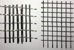
During concept design, an overlay product used extensively in Europe, Fabric-Reinforced Cementitious Matrix (FRCM), was being introduced to the California market by manufacturers including Simpson Strong-Tie. FRCM consists of either uni-directional or bi-directional carbon fiber fabric (Figure 2) embedded between lifts of cementitious matrix installed in ¼- to ½-inch lifts. The lifts can either be installed by hand similar to plaster, or as a spray installation similar to shotcrete. The fabric, which comes in rolls up to 77 inches wide, is pressed into the base lift before having a cover lift of matrix installed. The total thickness for one layer of FRCM is approximately 1 inch plus ½ inch for each additional layer of FRCM. As a porous cementitious material, FRCM is more homogeneous with existing brick stiffness and mechanical properties compared to epoxy-based overlays and allows the historic brick to breathe. The FRCM surface preparation only requires a surface clear of loose debris, cleaned, and saturated surface dry for cementitious matrix adhesion and curing. The FRCM can double as the base coat for plaster installation, removing an extra preparation step required for FRP.
The FRCM, combined with grout injection of large cracks in the brick substrate, was used to restore in-plane capacity to extensively cracked brick walls in place of typical traditional brick repair approaches. The matrix’s tolerance in lift thickness, and its ability to locally fill voids of up to 2 inches, provided flexibility for the structure’s variable (brick, concrete, and CMU) surface conditions and interfaces. Additionally, the FRCM was used to provide nominal continuity through structural elements such as floors and wall intersections using bundled splay anchor ties, laps between different materials, and nominal tension ties at reentrant corners exhibiting spandrel joint damage.
During design, Simpson Strong-Tie was in the process of gaining seismic approvals for FRCM in California. Therefore, the design process was a collaborative performance-based specification design-build approach. Simpson Strong-Tie acted as the engineer of record for the design of the FRCM product using American Concrete Institute (ACI) 549.4R-13, Guide to Design and Construction of Externally Bonded Fabric Reinforced Cementitious Matrix Systems for Repair and Strengthening Concrete and Masonry Structures, with direct input and oversight from ZFA. Per ACI 549.4R, there is no strengthening limit for earthquake and wind forces as they are not considered likely to damage the unprotected FRCM compared to a fire or blast loads. However, FRCM strengthening should not exceed 50 percent of the capacity of the original structure to limit force transfer to the brick. And, strengthening should be limited to 12-inch-thick walls maximum. Additionally, the combined brick and FRCM shear capacity should be compared to the limit state shear capacity of substrate toe crushing.
Based on the reduction in capacity determined in the damage documentation process, ZFA provided target minimum in-plane strengthening loads, ranging from 10 to 25 percent of the undamaged brick wall capacity, for the design of the FRCM to repair the wall to its undamaged capacity. ZFA also provided construction details for the installation of FRCM to walls and their intersections with surrounding structural elements. The design team coordinated the number of layers and directionality of FRCM on each wall face to minimize impact to significant architectural areas. The result was that each wall to receive FRCM had custom reinforcing layups, including at least one layer of bi-directional fiber reinforcing for continuity and added ductility.
Mockup
Due to the complexity of detailing and installing CMU, historic brick, wood framing, wall anchorage, and use of a new product in FRCM, the design team recommended the construction of a mockup. The mockup was intended to test installation techniques on similar conditions to the existing building and to identify potential issues before full mobilization during construction. The mockup served as a minimum quality of work example and later served as a surface for mockup of architectural finishes installed over the FRCM.
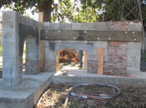
The mockup consisted of approximately 19 linear feet of a six-foot-tall wall in an ‘L’ configuration (plan view). It included the two typical window head configurations, an exterior corner pilaster, multiple CMU to brick interfaces, control joints, and a wood ledger to install FRCM splay anchors through. Once the structure was completed, FRCM was installed over each of the four sides on two separate days.
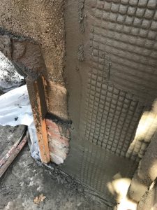
The mockup was completed early in the construction schedule and observed by the Design Team, Owner’s Representative, General Contractor, multiple representatives from Simpson Strong-Tie, and Project Inspector of Record (IOR). The group debriefed after each installation and circulated lessons learned. Through this process, multiple installation techniques were tested to ensure ½-inch lift heights. Ultimately, the most effective process was determined to be having preset feeler gauges, spot-checking the material as it was installed and using wires to set the final depth (Figures 3 and 4) similar to traditional shotcrete installation techniques.
Construction
As one of the first installations of the FRCM product in California, there were challenges to overcome. FRCM requires the substrate to be saturated surface dry (SSD). SSD is the condition at which the wall substrate is saturated, refuses to absorb additional water, and the surface is dry to the touch. The building has been enclosed for 140 years with central heat since the 1970s, which led the walls to be dry. The walls were wetted every 30 to 60 minutes during the day and covered overnight for approximately 48 hours before the walls reached SSD. This is critical to the installation of FRCM to prevent the wall substrate from absorbing the moisture in the thin lift layers of cementitious matrix, causing the material to flash or surface tear while the contractor finishes the installation. This challenge was not identified in the mockup because the mockup was new construction and was exposed to the outside elements before the installation of FRCM.
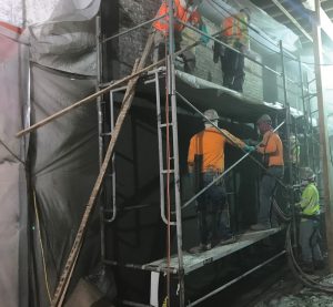
FRCM was installed with a pump, hose, and nozzle, similar to shotcrete. Typical shotcrete lifts are three to four inches minimum, meaning there was a learning curve to install the ½-inch lifts required for FRCM. The size of the walls complicated this. The typical wall height was 16 feet on the first floor and 18 to 20 feet on the second floor, requiring multiple levels of scaffolding to access (Figure 5). Matrix had to be installed around scaffolding, leading to shadowing and/or thin spots at the scaffolding planks and legs and thick spots at the corners, floors, and ceilings. These variations had to be trimmed to meet flatness requirements for future wall finishes. If the matrix was too thin, the fabric could be unintentionally moved or damaged while worked into the first lift of matrix.
Additionally, scaffolding presented an obstacle to the installation of the large rolls of fabric. The fabric could not be sharply bent without damaging the fiber bundles or disconnecting the unidirectional grid from tie strands. Therefore, the FRCM had to be installed from a rolled bundle challenging to work around scaffolding. While the mockup was an excellent proof of concept and uncovered many installation hurdles, it had size limitations that did not uncover challenges of large-scale construction means and methods.
Conclusions
FRCMs were used to provide in-plane and out-of-plane repair/strengthening throughout the building, maximizing the amount of historic brick wall that was preserved. Its relatively thin application, substrate tolerance, material compatibility with the existing brick, and its allowance for the walls to naturally breathe were critical to providing a structural solution while minimizing the effect on the historic character of the building (Figure 6). FRP would have required significantly more surface preparation in comparison to FRCM, and discrete shotcrete walls would have affected room sizes and required strengthening of collectors and foundations.
While FRCM had multiple benefits, using a new product to California presented several challenges during design and construction. These ranged from working with Simpson Strong-Tie as they developed design guidelines and material information, preparation of 140-year-old brick walls, and translating installation techniques from the mockup to working within the building. A dynamic and collaborative team approach was required by all involved to overcome these challenges.■

