
Addition, Renovation, and Rehabilitation at Hotel Julian
The condition of the building certainly did not match its high-profile location. For years, the existing 12-story building at 168 N. Michigan sat vacant on one of Chicago’s busiest thoroughfares. With an address on Michigan Avenue near the northwest corner of Millennium Park, countless residents and tourists would pass by each day. This empty shell was a once-prominent structure that had fallen into disrepair due to previous renovation attempts that were abandoned in mid-construction. Pieces of the original terra cotta façade had been removed, openings had been created in exterior walls and left uncovered, and the interior was in a similarly poor condition (Figure 1). During the design team’s walk-through at the beginning of the project, water that had penetrated the unsealed roof and traveled down 12 levels could be seen puddling on the basement slab.
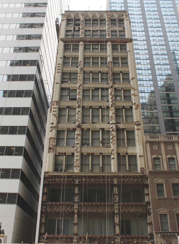
Figure 1. The exterior façade facing Michigan Avenue at the outset of the project.
The structure was originally constructed in 1911 as a bank office building and for decades occupied a place on the historic “Michigan Avenue Street Wall.” It utilized the popular structural system, of that era in Chicago, of clay tile flat arch slabs spanning to steel I-beams and built-up steel columns. These columns extended to concrete-encased steel grade beams and hand-dug concrete caissons. The lateral system consisted of masonry infill shear walls in the long direction of the building and built-up steel girder moment frames in the short direction.
Structural Scope
The original programming goal of providing a 200+ key boutique hotel ultimately required a structural scope that could be split into two categories: addition and renovation/rehabilitation. The addition came in the form of six new levels rising above the top of the existing structure, increasing the total building height from 160 to 240 feet and the square footage from 70,000 to 100,000. This significant increase required changes to the existing structure, renovations to accommodate programming changes, and repairs to in-situ conditions.
Addition
The design team’s first task was to assess the capacity of the existing structure to support the increased gravity loads from the 6-story addition. Field measurement and documentation of each column lift were required due to a lack of column information in the original structural drawings. Small coupons of the existing steel were taken and analyzed by a testing agency to determine the yield strength, ultimate strength, and weldability of the steel. Sonar testing of the existing concrete caissons, performed by the geotechnical engineer, was completed to determine the bearing depth and used to provide a design bearing capacity.
After a thorough review of the existing drawings and subsequent field investigation, structural analysis revealed that the existing columns and caissons were adequate to support the weight of the new addition. This was anticipated by the design team, based on a table listing assumed dead and live loads for future stories on a scrap sheet of the existing building drawings.
Unfortunately, it did not appear that the original designers accounted for the lateral load of a new addition. Although the 80-foot-tall addition increased the height by only 50 percent, it more than doubled the overall overturning moment on the building. The existing masonry shear walls (resisting loads against the short face of the building) were determined to be structurally adequate. However, the existing moment frames at the front and back of the building (resisting loads against the long face of the building) had no excess capacity to resist the new loads. A full-building 3-D analysis utilizing ETABS software revealed that all components of the moment frames were overstressed, from the bearing capacity of the existing caissons to the stress in the columns, plate girders, and riveted connections.
Additionally, deflections were determined to exceed the industry standard limits. This major shortcoming of the existing lateral system, but the adequacy of the gravity system, is most likely attributed to advances in lateral analysis and changes in code-required wind loads over the past century. Each moment frame would need to be wholly retrofitted or a new solution would need to be devised.
Strengthening the existing moment frames was considered and found to be infeasible since the size of the existing caissons limited the capacities of the frame. Therefore, an alternate system was required that would not disrupt the occupiable space, that could be erected inside of an existing structure, and which was stiff enough to draw load away from the moment frames. The solution was to install a hybrid lateral system consisting of two components throughout the full height of the existing 12-story building:
- Three new braced frames (Figure 2) adjacent to the elevator shafts were used for the main supplement to the existing lateral system. New columns were erected between the existing double I-beam girders and HSS braces were installed within the shaft walls at each level, extending down to the existing steel grade beams and up through the new addition. This allowed the new lateral component to fit seamlessly into the building while not impacting the architectural intent of the space.
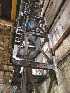
Figure 2. One of three new braced frames erected in the existing building.
- The steel braced frames were coupled with double angle steel knee braces (Figure 3), installed at approximately 175 locations throughout the interior of the building. This turned the existing interior double I-beam girders into link beams between the steel brace frames and knee braces. This provided the additional lateral stiffness required to draw load away from the exterior moment frames. This approach required local reinforcement of the existing columns against prying effects on the riveted built-up steel columns, but maximized the excess axial and bending strength of the interior columns.
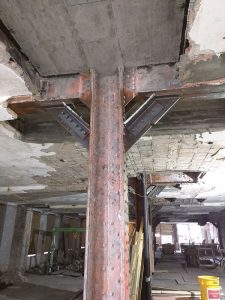
Figure 3. These double angle steel knee braces were installed at approximately 175 locations throughout the interior of the existing building.


In conjunction with the analysis and engineering associated with reinforcement of the existing structure, the six stories of the addition were also designed. Although the design of the new framing was straightforward, erection of the framing posed a significant challenge to the contractor. The constrained project site did not permit the use of a tower crane for steel erection. Neighboring buildings are present on the north and south sides, while the building is bounded on the east and west sides by public streets that could not be obstructed (Michigan Avenue and Garland Court, respectively). Instead, the design team and contractor collaborated to develop a method of supporting mobile cranes on the highest constructed floor in order to erect the next floor above, then raising the crane to that floor and continuing the process. For the first floor of the addition, the existing roof, this required reinforcement of existing beams and installation of a new composite slab-on-deck located inches above the existing clay tile slab. This floor and the subsequent floors above were designed for two uses: the load imposed by the mobile cranes during construction and the code-required loading in the final condition.
Renovation / Rehabilitation
The project also required significant renovation and rehabilitation to convert an early 20th-century building into a modern hotel, due primarily to the building’s condition at the start of the project. There were multiple periods of vacancy during its 105-year lifetime, including immediately before the project start. Water infiltration and exposure to the weather had compromised portions of the clay tile slab and caused significant corrosion of the steel framing in select areas. Some specific areas of rehabilitation included:
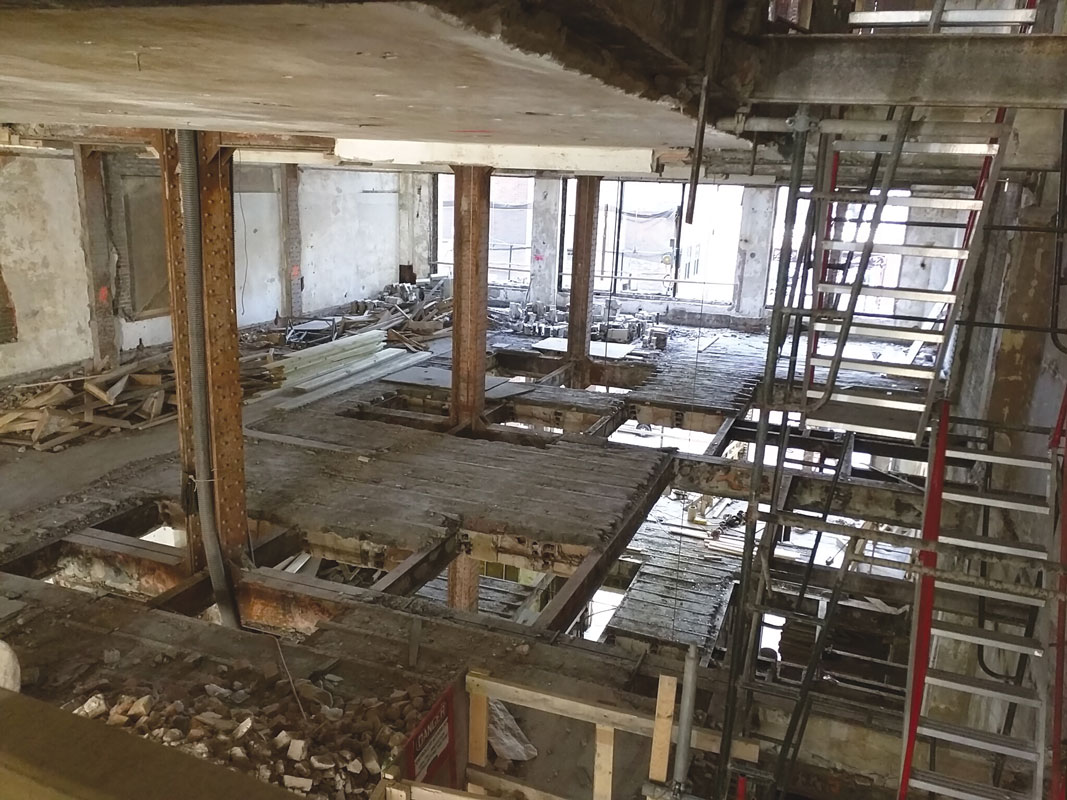
Figure 4. A typical level showing extensive demolition of the existing clay tile slab.
- Steel beams throughout the existing building were reinforced or replaced due to corrosion. The most extensive rehabilitation occurred at the existing roof, where full bays of steel beams were removed and replaced due to the extent of section loss. Investigations of the various conditions were performed to determine whether the beams were to be reinforced with plates or replaced with new beams.
- Previously abandoned renovation attempts created openings in the existing clay tile slab around nearly every existing column (approximately 200 locations) (Figure 4). These areas, combined with new demolition due to programming requirements, were infilled using a cast-in-place concrete system developed to reduce construction time and costs compared to a slab-on-metal deck infill. This was achieved by eliminating the need for field welding new beams and metal deck to the existing painted steel I-beams, which would have required costly lead abatement before welding. Eliminating the need for new steel beams at the perimeter of the openings also proved to be a key advantage due to the irregular sizes and shapes of the openings in the existing slab (Figure 3).
- The condition of the existing clay tile slab was reviewed throughout the building to identify areas of possible deterioration. Clay tile flat arch slabs are an archaic slab system that is susceptible to water damage in the mortar placed between the clay blocks. Standard patching/repair details were employed as much as possible, but several locations required complete removal of the existing slab.
The aforementioned cast-in-place concrete infill method was used to replace the existing slab at these locations.
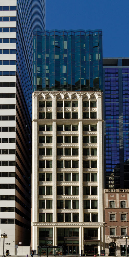
The rehabilitated exterior façade facing Michigan Avenue. Courtesy of Anthony May.
New Life for an Old Master
The existing building in the heart of Chicago’s downtown, once a candidate for demolition, received a much-needed rehabilitation. However, this was only part of the story. The ambitious goal of adding six levels to a 105-year-old building created an architectural highlight that stands out on this busy section of Michigan Avenue. Hotel Julian is now a modern hotel with a structure as impressive as its coveted location.■
Project Team
Owner: Oxford Capital Group, LLC
Structural Engineer of Record: TGRWA, LLC
Architect of Record: Hirsch MPG
General Contractor: W.E. O’Neil Construction