Salvaging History: Oakland’s Structural Rebirth
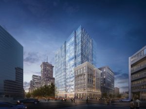
The Key at 12th is an 18-story office development in the heart of the central business district of Oakland, California. In an area where construction is booming and old buildings are being demolished all over the city to make way for modern facilities, Magnusson Klemencic Associates (MKA) was intrigued by the idea of designing a tower that repurposed a building rather than leveling it. Engineers worked side-by-side with architects and contractors to create a new structure that integrated the adjacent historic building, the 8-story Key Systems Building (KSB), into a combined development of 334,000 gross square feet (Figure 1). The project includes ground-floor retail, two occupied roof terraces, and is located next to a transportation hub. The Key at 12th is a textbook example of how the AEC industry can meld modern design with classic architecture, proving that progress can coexist with preservation.
Site History
The Key at 12th site occupies approximately one-third of a city block bounded by Broadway, 11th Street, and 12th Street, and originally contained the KSB and several low-rise structures. Significantly damaged in the 1989 Loma Prieta earthquake, the low-rise buildings were demolished and their one-level basements were filled with rubble up to grade. The KSB was also damaged and, unfit for occupants since the event, it stood vacant for the last 30 years. Several development projects had been proposed for the site, including a hotel and office. One project began installing approximately 80 precast piles on the bare site, and another project contemplated demolishing all of the KSB except for the façade and integrating the façade into a new building. Both projects stalled and were ultimately abandoned due to financial considerations, in part because of the cost to integrate the historically significant building but also because attracting tenants to a difficult site proved challenging.
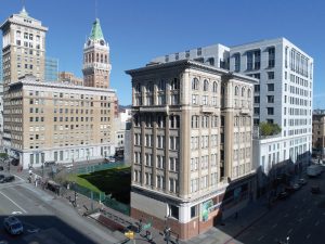
Finally, in 2017, Ellis Partners purchased the site and engaged Gensler to design an office building that integrated the KSB into the project in a manner that salvaged the existing structure while providing Class A office space. Preserving the KSB was a critical feature in successfully navigating the entitlement process, while creating a maximum-sized and highly-functional office floor plate was essential for attracting top-tier tenants (Figure 2).
Project Vision
Combining the dual goals of historic preservation and modern office design, the team configured a floor plan with a side-core layout to maximize the size of the office floor plate adjacent to Broadway, placing the elevators, stairs, and other core functions on the west side of the site, adjacent to another 12-story office building located on the property line. The building is split – the lower levels (1 through 8) combine a new structure with the existing KSB while the upper levels (10 through 18) are new construction. Gensler’s design merged new with old and function with form. The higher levels of office feature floor plates that cantilever approximately 25 feet over the KSB, resulting in maximum space and a design feature that combines and contrasts with the KSB.
The structural system consists of light-weight concrete slabs on composite steel decking, supported by steel framing. The cantilever is supported by two-story steel trusses located on the three exterior sides. To avoid interior trusses, MKA designed an approximately 100-foot-long exterior truss at the end of the cantilevered bay that transfers loads to 25-foot-long cantilever trusses located on the east and west perimeter sides of the building.
The tower’s lateral system consists of buckling-restrained braces (BRBs) and is comprised of single-story bracing configured in an E-shape at the core and two-bay, multi-story braces on the east side of the building to control torsion due to the offset core. With a roof height of 240 feet, the building is designed using the prescriptive requirements of ASCE 7-10, Minimum Design Loads for Buildings and Other Structures.
The foundation consists of a mat under the core on the western two-thirds of the site and a pile-supported grade beam on the west side of the site.
Integration of the Key Systems Building
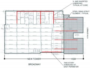
A central feature of this project was to bring new life to the vacant and dilapidated KSB. The building, constructed in 1911, is a steel-frame structure with concrete floors and masonry exterior walls. Consistent with buildings of this vintage, the structure did not have a well-defined lateral system. Rather than add intrusive and space-constraining new lateral elements within the KSB, the design solution was to use the new tower to buttress the existing KSB by adding diaphragm ties and collectors (Figure 3). The new tower’s lateral system was proportioned based on the mass of the KSB and designed to be stiff enough to protect the existing, brittle, exterior wall systems at the KSB. A series of north-south oriented collector elements were added at each floor to tie the KSB into the new tower diaphragms.
The existing south exterior masonry wall was removed after the two structures were connected to allow clear access between the KSB and the new tower. Also, the line of exterior columns located at the former perimeter walls was removed to provide a more substantial open office space. The relatively close-spaced columns (approximately 15 feet on-center) did not align with the columns of the new tower and would have created a forest of columns at the transition between the two buildings. The existing KSB framing that had been supported by these columns is now supported by cantilever steel beams extending from the new building columns. MKA worked closely with the contractor to sequence both the masonry wall and column removal to avoid extensive temporary shoring. Occupants will have an unobstructed view from the new building into the restored brick walls and wood windows of the KSB.
Lateral System Design
To minimize the building’s weight and to provide more flexibility at the interior of the side-core layout, a steel-braced lateral system was selected for the project. It was determined that an all-steel structural system was faster to erect than a concrete core. A braced frame was placed at the eastern perimeter along Broadway to control torsion and satisfy the requirements in ASCE 7-10 for the height increase to 240 feet for braced frame structures. To reduce the number of braces, provide a more open façade, and to meet the design intent of the architect, this perimeter brace is arranged in a multi-story “X” configuration and celebrated as a design feature visible through the curtain wall. The core bracing, which is generally hidden from view, was configured as single-story bracing in a chevron pattern to minimize the unbalanced loading on the beams.
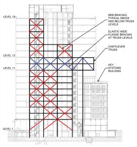
The main design challenge with the BRB lateral system was the interaction with the trusses supporting the cantilever. MKA’s design solution was to provide a two-story “elastic” zone at the level of the trusses (Figure 4).
Standard BRB framing exists above and below this level, but the two levels of truss floors utilize wide flange bracing designed for amplified seismic forces (omega) to force BRB yielding either above or below the transfer level. In addition, the trusses themselves were designed for gravity loads plus amplified seismic forces based on the relative lateral stiffness of the trusses compared to the other bracing elements on these floors. Ductile seismic performance is assured through yielding in the BRB elements, and stability is protected through the strength of the elastic zone elements.
The BART Influence
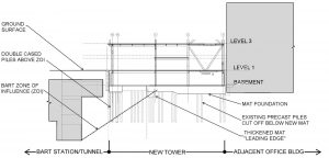
The Bay Area Rapid Transit (BART) system plays a significant role in the design of a building as engineers must consider and strategize ways to adapt a structure’s foundation around the tunnels. This poses many challenges. BART requires new developments adjacent to their tunnels and underground stations to limit any loading within the Zone of Influence (ZOI) to no more than the current load on the site. The ZOI is defined as a line starting from the lowest point of the BART structure adjacent to the subject property and extending up at a slope of 1.5 horizontal to 1 vertical until it hits grade (Figure 5). While downtown Oakland benefits from relatively good soils and an 18-story building using a light-weight steel structure could generally be supported on shallow spread footings or a mat, the proximity of the tower to the BART station required a different approach – deep foundations. Based on the depth of the tunnel and proximity to the site, the ZOI crosses the basement level approximately one-third of the way into the site. Therefore, all structural elements located in this third of the site needed deep foundation elements to transfer the load below the ZOI. The Key at 12th utilizes double-cased auger cast piles (24-inch piles within 33-inch steel casings) above the ZOI that are effectively free-standing concrete columns within the ZOI. Lateral forces are transferred from the perimeter braced frame back to the mat foundation through a basement-level transfer slab.
The site beyond the ZOI is founded on a concrete mat that varies from 5 to 7 feet at the core. The column layout for the tower was based on three bays in the east-west direction with the first interior column located on the mat foundation. However, during design, additional as-built information on the BART tunnel depth revealed the tunnel to be slightly deeper than initially anticipated. This required the mat’s leading edge be thickened by 4 feet to bear outside the ZOI.
A Development for Oakland’s Future
Expected to open in early 2020, The Key at 12th continues the rebirth of downtown Oakland while preserving one of the architectural treasures of its history. As cities continue to change, grow, and modernize, projects such as the Key at 12th show that we can successfully integrate old and new construction.■

