
Design and detailing of handrail anchorages in concrete structures must consider both structural performance and susceptibility to corrosion. Without these dual considerations, handrail anchorages are more likely to fail. For decades, premature corrosion of handrail anchorage components was prevalent in the concrete industry. Deterioration of the anchor embedments due to galvanic corrosion, direct exposure of aluminum to concrete, or insufficient concrete cover resulted in costly repairs.
While improvements in structural detailing and material selection to mitigate corrosion have been successfully implemented and are now common practice, the structural design and installation of handrail anchorages remains a minefield. A primary cause of continued handrail anchorage issues is the lack of clear delineation of design responsibilities and detailed coordination between the architect, handrail system manufacturers, the engineer of record, and the contractor. As a result, inappropriate assumptions and poor communication remain a source of deficient handrail installations.
Repair of structurally deficient rail-post anchors is both challenging and costly. Rail-post anchorage repairs often must maneuver tight geometries, a concrete substrate congested with steel reinforcement, numerous forms of potential corrosion cells, and elevated access limitations. This article presents a novel repair solution that was used to address structurally deficient handrail anchorages in a high-rise building. The repair approach presented herein uses inert materials that are not susceptible to corrosion due to environmental exposure.
Handrail Anchorage Assemblies – The Basics
The International Building Code (IBC) specifies the minimum applied live loads on balcony railings. The effects of live and wind loads need to be considered when designing handrail components. The selected anchorage system should resist the effects produced by a 200-pound concentrated live load or a 50 lb/ft linear live load applied directly at the handrail, as well as location- and elevation-specific wind loading. The applied loads are transmitted from the railing posts into the anchorage assembly and the concrete slab.

Figure 1. Free body diagram for the anchor reaction forces produced by handrail loading. Adapted from Raths 1974.
The post anchorage should be designed to resist the effects of the externally applied shear force and moment couple, without causing breakout failure of the concrete slab. Calculating the force that is developed within the anchor is not straightforward. This is particularly true for anchorages embedded into the concrete slab. Several published analytical methods can be used to provide rational estimates of the reaction forces that develop within the anchorage assembly due to externally applied shear and moment forces. The free-body diagram shown in Figure 1 is based on the findings reported by Raths (1974) for steel embedments in concrete at the ultimate state. The externally applied handrail forces are resisted by a shear couple (CF and CB) that develops within the embedded depth of the anchorage assembly. The free-body diagram can be used to calculate the breakout shear demand (CF). It should be noted that Figure 1 does not include wind loading for simplicity, but the demands due to wind loading can be included similarly. In addition, a load reversal is possible but results in smaller concrete breakout stresses due to the relative magnitudes of CF and CB per the equation, (CF = VU + CB).
Handrail anchorage assemblies in concrete elements are designed following the requirements of Chapter 17 of ACI 318-19, Building Code Requirements for Structural Concrete. According to ACI requirements, the breakout shear force can be resisted by either the shear breakout resistance of the concrete material at the slab edge or anchor reinforcement. Unlike one-way beam shear strength requirements, the contribution of the concrete resistance and the anchor reinforcement cannot be added when calculating the breakout shear strength.
The concrete shear breakout strength is proportional to the distance separating the anchorage embedment and the slab edge and is calculated using the formulas in Section 17.5.2 of ACI 318-19. In typical balcony installations, the edge distance is minimized to increase usable balcony space. As a result, the concrete breakout strength is marginal and often insufficient to resist the applied design forces. Hence, anchor reinforcement, commonly steel hairpins (U-shaped reinforcement with legs extending back into the slab), are used to reinforce typical anchorage assemblies in concrete balconies. Article 17.5.2.9 of ACI 318-19 permits the use of properly developed hairpin anchor reinforcement to resist the applied breakout forces. Because the concrete breakout strength is marginal, failure to provide anchor reinforcement around handrail posts due to improper design or installation can lead to anchor failures. The following discussion examines a case study of deficient handrail anchorages and the repairs performed to ensure adequate structural performance.
A Hidden Deficiency
Rail-post anchorage deficiencies were discovered during slab-edge repairs on an 8-year-old high-rise condominium. The slab edge repairs were performed to address the widespread corrosion of steel reinforcement. The premature corrosion was the result of improper placement of reinforcing bars along the post-tensioned (PT) slab edges in the 54-story building and mostly unrelated to the rail-posts anchorages. The repairs included removal and replacement of more than 1.5 linear miles of slab edges directly exposed to weather. To mitigate future corrosion problems, the repairs utilized glass-fiber-reinforced polymer (GFRP) bars to reinforce and anchor the newly cast slab edges.
The balcony railing system at the building consists of an aluminum frame with glass panels. The railing posts are embedded into 4-inch-deep grout pockets that were blocked out during placement of the 5.5-inch-thick PT slabs. The blockouts were later filled by no-shrink, high-strength mortar after the railing posts were secured in place. The original design called for No. 5 steel hairpin reinforcement to be placed around the grout pockets with a top concrete cover of 1 inch. The diameter of the grout pockets is approximately 4 inches, with the centerline of the pockets located 3 to 6 inches from the slab edge. As a result, the distance between the outer edge of the grout pocket and the slab edge ranged between 1 and 4 inches. The rail post-block-out position and depth contributed to congestion and low reinforcement cover in the vicinity.

Figure 2. Concrete removal along a slab edge exposed grout pockets with missing hairpin anchor reinforcement.
During the early stages of repair construction, the contractor exposed railing post anchorages that did not have the No. 5 hairpin anchor reinforcement as specified in the original design (Figure 2). The issue of missing anchor reinforcement was only observed at the bottom four stories of the residential tower. A review of the original construction documents suggested that the culprit for the missing anchor reinforcement was likely miscommunication between the structural engineer, the railing system manufacturer, and the contractor.
As constructed, the railing anchorages with missing anchor reinforcement were structurally deficient and did not comply with building code requirements. Due to the limited edge distance between the grout pocket and the slab edge, the post anchorages were susceptible to breakout if design-level, or even service-level, loads were applied. Hence, structural repairs to strengthen the deficient anchorages were necessary.
A Novel Repair Approach
Given that the existing and repaired slab edges did not have sufficient breakout strength to resist the design loads, it was evident that mechanical strengthening using post-installed reinforcement was needed. However, the use of drilled-in, post-installed steel anchor reinforcement was not a feasible option. To adequately develop a post-installed anchor reinforcing bar beyond the breakout failure plane, minimum 12-inch-deep holes had to be drilled into the slab substrate. Due to steel congestion near the slab edge and the presence of PT tendons and anchor components, the risk of accidentally damaging existing reinforcement and PT tendons during drilling was substantial. The steel congestion near the slab edge mitigated the use of non-destructive testing methods to reliably locate embedded PT components before drilling.
The repair team also considered using externally applied carbon-fiber-reinforced polymer (CFRP) sheets to strengthen the slab edges around the post anchorages. However, due to the slab edge geometry and the presence of a drip edge along the slab soffit, the CFRP sheets could not be adequately developed. Furthermore, the repaired slab edges were to remain exposed, with only a thin layer of elastomeric coating. Hence, the surface applied CFRP sheet fibers would have visibly affected the aesthetics of the repair.
Given the numerous project restraints, the repair team determined that near-surface mounted (NSM) reinforcement was an ideal solution. NSM reinforcing bars are embedded within purposely prepared surface grooves using epoxy. Stresses are transmitted from the reinforcing bar to the epoxy and then to the concrete substrate through mechanical bond. Because the NSM grooves do not extend more than 1.0-inch-deep into the slab, the risk of damaging existing reinforcement or rupturing PT tendons is mitigated. The epoxy-filled NSM grooves can be leveled with the top concrete surface, which is eventually coated with an elastomeric waterproofing membrane. Also, a top surface placement is most effective in resisting the moment resulting from applied forces. Hence, the NSM reinforcement solution has little to no impact on the repair aesthetics and effectively resists the design forces.
If poorly detailed or constructed, the use of steel reinforcement in NSM repairs can lead to premature corrosion. To mitigate corrosion risk, the design team opted to use GFRP hairpin reinforcement for the handrail anchorage repairs. GFRP bars are electrochemically inert and are not susceptible to corrosion, regardless of the exposure conditions.
ACI 440.2R-08, Guide for the Design and Construction of Externally Bonded FRP Systems for Strengthening Concrete Structures, provides design provisions and construction guidelines for NSM systems with FRP bars. The size of the GFRP bar is first determined by evaluating the tensile capacity of the bar. The tensile strength of GFRP reinforcement must be reduced to account for environmental exposure effects. Also, the tensile strength of GFRP reinforcement with bends (for example, hairpins) is further reduced to account for the stress concentrations that can occur within the bend region. ACI Committee 440 provides guidelines for minimum allowable GFRP bend radii to alleviate the stress concentrations at the bend locations. The repair specifications in this project also restricted the allowable amount of cross-sectional distortion of the bends to reduce the effect of manufacturing discrepancies on stress concentrations.
Based on the calculated demands, the analysis determined that a No. 3 GFRP hairpin was sufficient to provide anchor reinforcement for each handrail post. The length of the hairpin legs was determined based on the bond strength criteria provided in Section 13.3 of ACI 440.2R. For the selected bar dimensions and load demands, a development length of 12 inches was needed. The surface groove dimensions were detailed based on the ACI 440 guidelines. The minimum specified depth and width of the surface grooves (¾ inch) were greater than 1.5 times the GFRP bar diameter. Also, the groove surfaces had to be roughened and cleaned before installation of the epoxy adhesive and the GFRP bar.
Because slab edge repairs were in progress immediately adjacent to the rail posts, measures had to be developed to reliably incorporate the NSM repairs into the newly cast slab edges. To this end, the repair engineer provided two alternatives for the contractor. The first alternative allowed for placing a blockout over the newly cast slab edge to form the needed NSM groove. This option was ideal if the slab edge repairs at a given location needed to be performed before the NSM installation. The blockout is then removed, and the groove surfaces are prepped and cleaned before the GFRP hairpin installation.

Figure 3. Details for typical NSM GFRP hairpin repair.
If the NSM installation could be performed before the slab edge was cast, the contractor was allowed to embed the curved portion of the hairpin into the repair concrete. Because the thermal expansion properties of concrete and GFRP are different, the design specified an increased concrete cover over the portion of the GFRP hairpin embedded in concrete and not epoxy. Shallow concrete cover over GFRP bars can result in cracking due to a thermally-induced strain differential between the concrete and the GFRP material. As such, while a clear cover of ⅛ inch was sufficient for portions of the GFRP bars covered with epoxy, a more significant cover was needed for portions embedded in concrete. Per ACI 440 guidelines, the portions of the GFRP hairpin that were embedded in concrete had a vertical cover of at least ½ inch. This was achieved during construction by gradually increasing the depth of the NSM groove as the distance to the slab edge decreased. Figure 3 schematically shows the repair details, and Figure 4 shows a GFRP hairpin soon after installation.
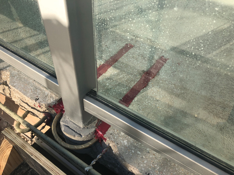
Figure 4. GFRP hairpin installed around a railing post grout pocket.
The repair contractor was able to perform the repairs without removing the railing components, which further reduced the cost of the repairs. The groove edges were created using shallow saw cuts, and then 15-pound chipping hammers were used to remove the concrete within the sawcut boundaries. The groove surfaces were roughened per ACI 440 requirements to improve the bond between the epoxy and concrete substrate. The epoxy adhesive selected for the NSM repair was chosen based on reported past performance and recommendations of the GFRP bar manufacturer. During NSM repair execution, the railing system in each of the affected balconies was temporarily supported in the out-of-plane direction, and public access to balconies was restricted to prevent failure of the handrail system during repair execution.
Conclusion
The use of fiber-reinforced-polymer bars in concrete construction has increased rapidly over the last few decades. Due to their inherently inert characteristics, GFRP bars provide an attractive solution for structures in corrosive environments. As demonstrated here, GFRP reinforcing bars are a viable solution for use in repair projects. The limitations and challenges encountered in this project were not unique or isolated, and this repair option provided an effective means of avoiding the traditional pitfalls of conventional rail post anchorage repairs.■
References
ACI Committee 318. (2019). Building Code Requirements for Structural Concrete (ACI 318-19). Farmington Hills, MI: American Concrete Institute.
ACI Committee 440. (2008). Guide for Design and Construction of Externally Bonded FRP Systems for Strengthening Concrete Structures (ACI 440.2R-08). Farmington Hills, MI: American Concrete Institute.
International Code Council. (2015). 2015 International Building Code. Country Club Hills, IL: International Code Council.
Raths, C. H. (1974). Embedded Structural Steel Connections. PCI Journal, 104-112.