
Part 2: SMI Concrete Flat Plate and Site Safety Demolition Plan Peer Review
This four-part series (Part 1, STRUCTURE, November 19) discusses how the collapse of a building during a demolition operation in Philadelphia in 2013, which resulted in several fatalities, led to the enactment of a City Ordinance to prevent similar future calamities. As a result of the Ordinance, the author became involved with the structural investigation, review of the Site Safety Demolition Plan, and Demolition Special Inspections associated with the adaptive reuse of the Apex Hosiery Company Building located in Philadelphia.
SMI System
The SMI System (Smulski Method) of designing and constructing reinforced concrete flat plate slabs was developed prior to the 1920s by Edward Smulski, a consulting engineer from New York City. The system was unique in that the primary flexural reinforcement consisted of concentric rings of smooth reinforcing bars supplemented with diagonal and orthogonal trussed bars placed between the supporting columns, and radial hairpin bars located at the columns as shown in Figure 7. The rings consisted of smooth bars which were lapped at the ends to develop their full strength. The laps of the concentric rings were also staggered to avoid adjacent laps from occurring at the same radial location within each group of concentric reinforcing.
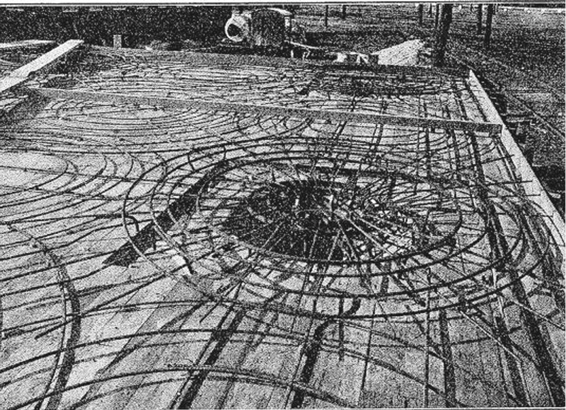
Figure 7. The primary flexural reinforcement for the unique SMI system.
The concentric rings of the SMI System were located in the top of the slab directly above the columns, in the bottom of the slab at the mid-span of what is now referred to as a column strip, and in the bottom of the slab at the mid-span of what is now referred to as a middle strip, centered in the bay formed by the column grids. There was no top reinforcing provided in the middle strip at the intersection with the column strips, as is now required by the building codes. The concentric rings of bottom reinforcement also overlapped at the interface zones while the top reinforcement above the column overlapped the bottom bars below.
The theory behind the design of the SMI System was based on the same flexural theory of reinforced concrete used by other methods of analysis at the time, in that bending moments were resisted by internal stresses in the concrete, compressive on one side of the neutral axis of the section and tension resisted by reinforcing on the other. The primary difference with the SMI System is that the tensile stresses in the structure are offset by the concentric rings of reinforcing bars, which resisted the tendency of the concrete within the ring to deform and elongate due to the tensile bending forces. So, in other words, the rings were subjected to hoop stresses in which axial tensile forces were induced in the rebar via the perpendicular radial forces of the concrete tension.
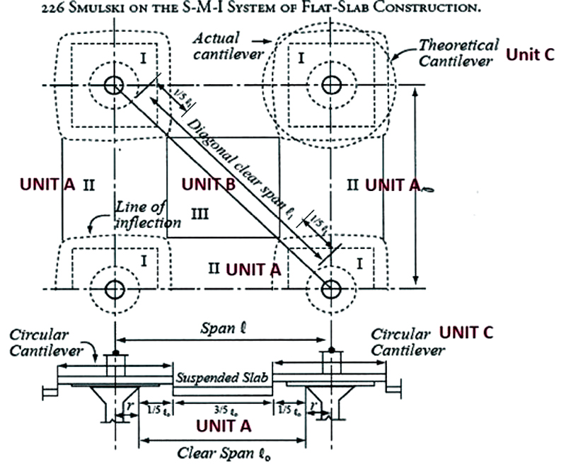
Figure 8. The slab was separated into three independent sections as a part of the structural design.
The slab was separated into three independent sections as a part of the design of the system, as shown in Figure 8. The column head was analyzed as if it were a circular cantilever fixed at the column and loaded uniformly around its circumference. The orthogonal and diagonal slab clear spans between the columns were analyzed for positive bending moments only. The hoop reinforcing for all of the sections was calculated as indicated in Table 1. Comments by one of the authors of the 4th Edition of Plain and Reinforced Concrete, Volume 1, published in 1925, indicates that the SMI System required 20 to 24% less reinforcing than comparable two-way and four-way flat slab systems that were constructed during the same time period.
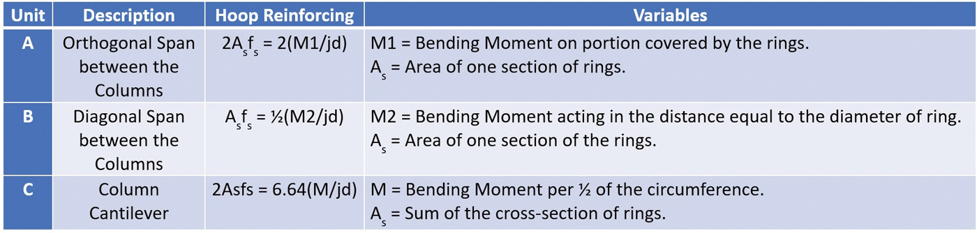
Table 1. Calculated hoop reinforcing for all three slab sections.
Load tests of the SMI System were conducted at Purdue University prior to 1920 with the results published in the 1918 ACI Journal Proceedings. Stresses within the reinforcing rings were measured using an “extensometer” developed by Professor Claude Berry of the University of Pennsylvania. The 41-by 36.5-foot, 2×2 bay test frame, with cantilevers on three sides and an upturned spandrel beam on the fourth, was loaded using bricks stacked in such a way to prevent arching action of the masonry units. The center-to-center spacing of the columns was 16 feet. All columns included a capital. The slab thickness was 5½ inches. The test frame was loaded from 150 psf to 950 psf until failure occurred.
The principals of circumferential and radial bending moment analysis were also being researched at the University of Wisconsin in the early 1900s. A discussion of the methods of analysis can be found in the Principals of Reinforced Concrete Construction, 3rd Edition, published in 1919. Also, before the development of the SMI system, another similar reinforced flat slab method of framing was patented in 1911 by Claude Turner. Mr. Turner, who referred to his method of design as the “Mushroom” flat slab system, developed the method of construction in Minneapolis, Minnesota.
The available literature that deals directly with the SMI Systems indicates that Edward Smulski patented the method of construction. However, a cursory search through the U.S. Patent Office indicates that there were only two patents granted to Smulski, one for a cast-in-place counterfort system for retaining, reservoir, and dam walls and one for a two-way, orthogonal reinforced slab system that included encased steel beams. It is also not clear how prevalent the use of the SMI System was during both the early 1900s and later in the century. The author is only aware of one other SMI structure in Philadelphia, and the number of structures that were constructed or currently remain that were built using this system is unknown.
In the author’s opinion, it is not likely that this system was used to a large degree or was very popular because of the assumed difficulty associated with properly fabricating and placing perfectly round and concentrically positioned bars in overlapping top and bottom layers. In addition, based on the challenges associated with the renovation of the Apex building, the SMI system was more susceptible to the introduction of new mechanical and utility openings required in the framed floor slab than the southern, conventionally reinforced two-way flat slab.
Peer Review of Site Safety Demolition Plan (SSDP)
Structural analysis of the existing building was completed as a part of the peer review of the SSDP and to determine the feasibility of the proposed adaptive reuse of the building. For the peer review, a separate analysis of the structure, in addition to what had previously been completed as a part of the original SSDP, was required for three primary reasons:
- The engineer reviewing the SSDP had assumed that the entire existing building was constructed with only a conventionally reinforced two-way slab and was not aware of the presence of the SMI system on the north side of the building.
- The analysis had only considered the weight of the mechanized demolition equipment and not the anticipated piles of debris.
- The analysis/modeling of the two-way conventionally reinforced slab had not been performed correctly.
The peer-review analysis involved determining if the existing two-way concrete slab could simultaneously support the proposed mechanized demolition equipment and piles of debris created during the demolition operation. Also, the results of the analysis were used to assess the proposed sequence of demolition to determine if the remaining portions of the structure would continue to be stable as adjacent bays of framing and columns were removed.
The methods of analyzing the existing structure used by Pennoni for the proposed approach to demolishing the upper levels of the building were also the same as what will be described for the feasibility study analysis included in Part 3 of this article. However, the method of analysis used by the original SSDP engineer involved a finite element model (FEM) of three bays of a typical framed level in both directions. Unfortunately, the model did not
- Include the existing column capitals or drop panels
- Use accurate bay dimensions
- Assume the correct slab thickness

Figure 9. Example of an incorrect method of flat slab FEM via pinned supports at the column that was used in the SSDP.

In addition, the column support locations were modeled as a cluster of four closely spaced pinned connections associated with the location of the FEM mesh. Figure 9 illustrates an example of this incorrect method of modeling a flat slab via pinned supports at the column that was used in the SSDP, while Figure 10 shows the correct method that also engages the column supports in the story above and below the slab.
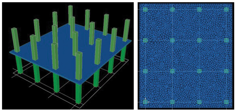
Figure 10. Correct FEM method that engages column supports in the story above and below the slab.
As a result of modeling an individual column as a group of four pinned supports in the FEM, an exaggeration of the magnitude of negative moments that could be transferred to the columns occurs. This is because the pinned supports, at any one column location, result in a point of fixity that does not accurately represent the interaction between the slab and the flexible, story-high column stiffnesses above and below the slab. As a result, the SSDP model underestimated the positive moment at the column and middle strips by approximately 24%, as illustrated by a comparison of the outputs shown in Figures 11a and 11b. Also, the SSDP engineer did not include an analysis of the punching shear effects around the column supports, as required by the ACI 318, Building Code Requirements for Structural Concrete and Commentary.
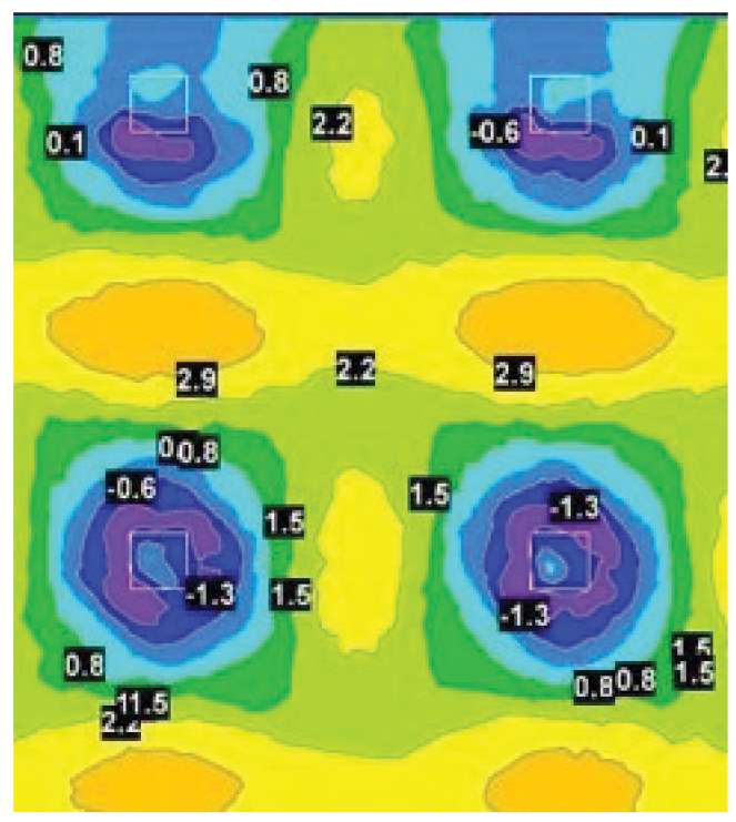
Figure 11a. The SSDP FEM underestimated positive moments at column and middle strips by approximately 24%.
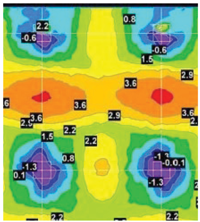
Figure 11b. The properly modeled FEM results in correct positive moments at the column and middle strips.
Conclusion
The Site Safety Demolition Plan review associated with the adaptive reuse of the Apex Hosiery Company Building located in Philadelphia involved an analysis of the unique SMI system of reinforced concrete flat plate slabs and a review of the SSDP FEA of other areas of the building. Part 3 of the series will provide an overview of the feasibility analysis for the slab retrofit.■