
Anchoring-to-concrete provisions in the American Concrete Institute’s Building Code Requirements for Structural Concrete (ACI 318) are used to calculate anchor design strengths that consider possible anchor failure modes. These design strengths are checked against calculated factored loads acting on anchors. ACI 318 anchoring-to-concrete parameters for calculating anchor design strengths are derived from testing and analysis that includes the use of a rigid fixture to apply tension load to anchors. Therefore, ACI 318 provisions for anchor design can be considered relevant if the fixture being attached can be considered “rigid.”
A rigid fixture is assumed to have a cross-section that remains plane under loading and does not undergo deformation from bending. However, for some anchoring-to-concrete applications, a rigid fixture assumption may not be valid, thereby precluding the use of ACI 318 anchoring-to-concrete provisions to design the anchorage. Finite Element Modeling (FEM) provides a means to assess whether a rigid or non-rigid fixture assumption is valid. This article explains how finite element modeling can be used to analyze a fixture and how the results of this analysis can be interpreted for the design of a concrete anchorage.
Why Finite Element Modeling?
Structural and nonstructural components are attached to a concrete member using cast-in-place or post-installed anchors. Tension load, shear load, and moments acting on the component are transferred into the anchors through a plate or other fixture. Determining the tension load distribution on the anchors from the loads acting on the component is necessary to design the concrete anchorage. If the fixture being attached is assumed to be rigid, the tension load distribution on the anchors can be calculated using strain compatibility relationships (PL/AE) and basic statics (Σ forces and Σ moments). Figure 1 illustrates how strain compatibility relationships can be utilized in conjunction with a rigid fixture assumption to define the tension load distribution on a group of anchors. Assuming the fixture is rigid permits the stress/strain distribution to be defined as linear, which allows for the use of similar triangles to define the tension load distribution on the anchors and the compression stress in the concrete beneath the fixture.
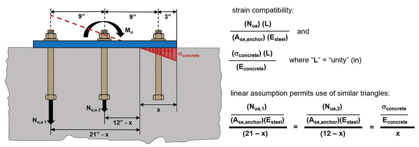
Figure 1. Rigid fixture strain compatibility relationships.
The linear stress/strain distribution assumed for a rigid fixture permits a simplified approach for calculating tension loads on anchors. It is important to keep in mind that ACI 318 anchoring-to-concrete provisions are predicated on a rigid fixture assumption. Tension loads acting on anchors must be checked against the calculated anchor design strengths for each relevant anchor failure mode.
The magnitude of anchor tension loads calculated using a rigid fixture analysis will typically be less than the magnitude of anchor tension loads calculated using a non-rigid analysis. A rigid fixture analysis assumes the stress in the fixture resulting from the tension loads acting on it is less than the fixture yield stress. Prying action causes a non-rigid fixture to bend and possibly yield, resulting in the displacement of the fixture and tension load re-distribution among the anchors. The stress/strain distribution for a non-rigid fixture subjected to prying action will be non-linear, and the analysis to determine tension loads acting on the anchors becomes more complex.
ACI 318 anchoring-to-concrete provisions include parameters to account for the resultant tension load acting on an anchorage being eccentric with respect to the centroid of the anchors in tension. The parameter Ψec,N is used to calculate nominal concrete breakout strength in tension, and the parameter Ψec,Na is used to calculate nominal bond strength. Ψec,N and Ψec,Na include a parameter for eccentricity (e´N) that corresponds to the distance of the resultant tension load from the centroid of the anchors in tension. The equations to define Ψec,N and Ψec,Na, as well as the analysis to determine e´N, are predicated on anchor attachment with a rigid fixture. Therefore, calculating e´N using a fixture that exhibits non-rigid behavior could lead to unconservative calculation results for Ψec,N and Ψec,Na.
When one is unsure if a rigid or non-rigid fixture assumption is valid, FEM can be used to ascertain the following:
- The stress magnitude in the fixture
- The strain magnitude in the fixture
- Does the fixture undergo prying action?
- Anchor tension loads for rigid versus non-rigid behavior
Non-rigid fixture behavior cannot be analyzed using algebra, but it can be analyzed with software that performs FEM. “Discretization” is the critical FEM parameter. Consider a plate with a uniformly distributed load acting on it, as shown in Figure 2. The reactions at the fixed boundary can be determined using FEM.
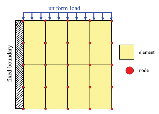
Figure 2. Discretization using finite element modeling.
“Discretization” means “dividing into elements.” The uniform load in Figure 2 is transferred to the fixed boundary by square elements that are connected via “nodes.” Load transfer only occurs at nodes. Reactions at the fixed boundary are obtained in terms of stress and strain. The accuracy of the calculated reactions will increase the more the plate is discretized. A structure can be discretized using different types of elements. One-dimensional elements are typically used for load analysis (based on stiffness) in most structural analysis software. FEM for anchoring applications uses two-dimensional elements modeled as a plate/shell. Three-dimensional elements are used for complex applications such as machine design.
FEM provides a realistic analysis of a material’s engineering and mechanical properties by considering stiffness. The ability of a material to transfer load can be accounted for via its stiffness. FEM utilizes a matrix algebra equation {F} = [k] {d}; where “k” corresponds to a stiffness matrix, and “d” corresponds to the displacement matrix that results from forces “F” created within the element. Displacements correspond to the degrees of freedom modeled at each node.
Component-Based Finite Element Modeling
Typically, structural analysis software that uses FEM models load-carrying members such as beams and columns as a one-dimensional element. Load must be transferred from one member to another via a connection. Typically, connections must be designed separately, either in a spreadsheet or as a separate FEM application. Component-Based Finite Element Modeling (CBFEM) software permits calculation of all relevant component loads without separate analysis.
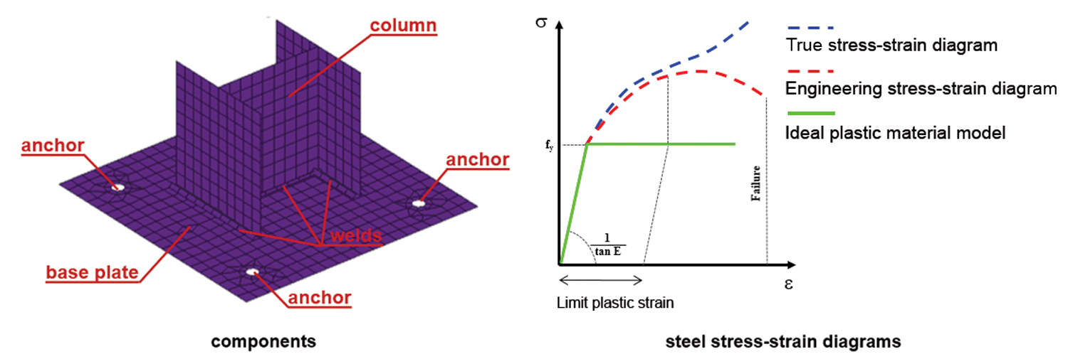
Figure 3. Component-based finite element modeling. Courtesy of IDEA StatiCa.
CBFEM models steel components, such as a base plate or column, as a plate/shell element. This material behavior can be depicted by Von Mises yield criterion, which assumes the element behaves elastically before yielding. The green bi-linear stress/strain curve in Figure 3 illustrates this material behavior. Strain hardening (plastic strain), defined by the horizontal portion of the green curve, occurs after yielding.
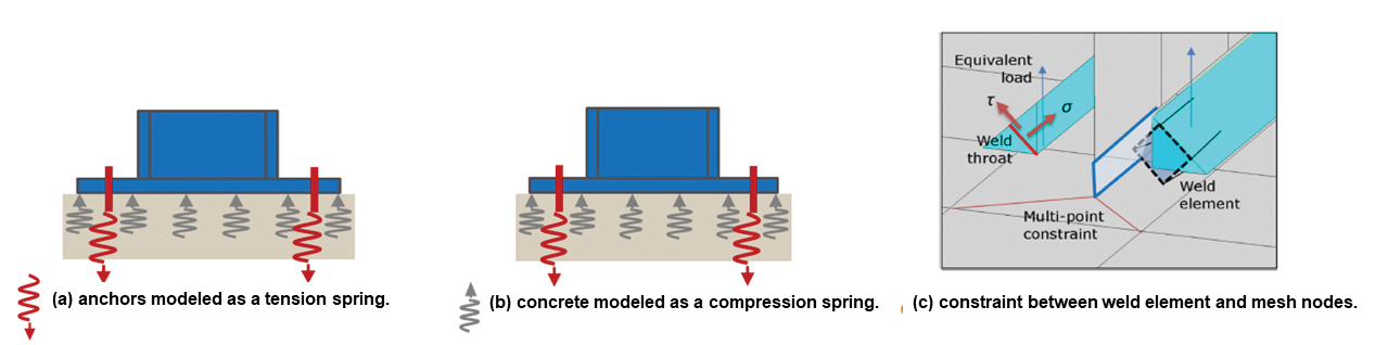
Figure 4. Component based finite element modeling of a steel column anchorage. Courtesy of IDEA StatiCa.
Consider a steel column anchorage modeled using CBFEM. The column and base plate are modeled as two-dimensional shell/plate elements. Anchors are modeled as a tension-only “spring,” as illustrated in Figure 4a. Under tensile or bending load, the base plate deforms due to the force distribution resulting from the stiffness of the shell/plate elements. This base plate deformation causes the “spring” to elongate by an amount (d). Anchor stiffness (k) is associated with the spring elongation. The product of anchor stiffness (k) and displacement (d) is used to calculate the tension force (F) transferred to the anchor per the matrix algebra equation {F} = [k] {d}.
CBFEM uses a Winkler-Pasternak subsoil model to represent concrete deformation numerically. This permits the concrete interface to be defined as two-dimensional compression-only springs (Figure 4b). Concrete stiffness is determined using the concrete modulus of elasticity (Ec).
Welds between the column profile and base plate are modeled as load deformation constraints, defined by special plate elements, that simulate load transfer through the weld (Figure 4c). The model defines the weld as a connection between two plate/shell elements: one element on the column profile and one element on the base plate. The element nodes are not directly connected. A midline surface of the connection between two plate/shell elements is modeled with an offset, which represents the weld geometry. If fillet welds are used, weld stresses are calculated in the throat.
Rigid Versus Non-Rigid Analysis
CBFEM can be utilized to determine if a fixture exhibits rigid or non-rigid behavior; however, using CBFEM to obtain a design solution must also be considered. Steel design codes, such as those published by the American Institute of Steel Construction (AISC), only include provisions for rigid base plate analysis to determine anchor loads. However, AISC publications do not preclude non-rigid base plate analysis to determine anchor loads. Anchor design strengths calculated per ACI 318 anchoring-to-concrete provisions are predicated on the attachment of a rigid fixture, which can be assumed to act as illustrated in Figure 5a and Figure 5c. If the anchor loads are calculated assuming non-rigid fixture behavior, as illustrated in Figure 5b and Figure 5d, ACI 318 anchor design strengths checked against these loads could result in a misinterpretation of ACI 318 code provisions.
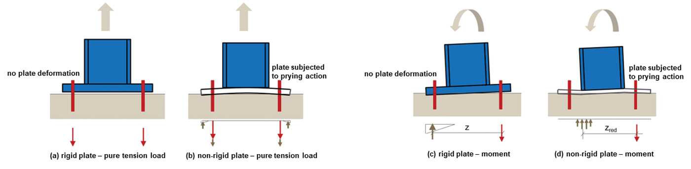
Figure 5. Rigid and non-rigid plate behavior.
Consider a column subjected to pure tension load. A non-rigid base plate will tend to deform, as shown in Figure 5b. This deformation induces “prying” forces in the plate, which create increased tension load on the anchors.
Now consider the column with a moment acting on it. If the plate is rigid, it will rotate, but its cross-section does not deform (Figure 5c). A triangular stress distribution is assumed to occur beneath the plate, where it is in contact with the concrete. The moment arm (z) corresponds to the distance between the anchors that are in tension and the centroid of the triangular stress distribution. If the plate is non-rigid (Figure 5d), it will rotate and deform. The moment arm (zred) corresponds to the distance between the anchors that are in tension and the centroid of the compression stress distribution beneath the deformed part of the plate, where it is in contact with the concrete. zred (Figure 5d) is less than z (Figure 5c) because the non-rigid plate deformation causes the compression stress distribution to shift from a location close to the edge of the plate to a location closer to the perimeter of the column profile. If forces and moments are summed to calculate tension load on the anchors, the smaller lever arm zred will result in higher tension forces on the anchors, illustrating how the magnitude of anchor tension loads calculated using a non-rigid fixture analysis will typically be greater than the loads calculated using a rigid analysis.
Parameters for CBFEM
Plastic strain, as depicted by the horizontal portion of the green bi-linear stress/strain curve in Figure 3, is initiated at yielding. A limiting plastic strain can be expressed as a strain percentage beyond the strain at yielding. Steel design codes in the United States do not have provisions to limit the amount of plastic strain. The Eurocode recommends limiting the amount of plastic strain beyond yielding to a value of 5%. Therefore, setting a limit on the “permissible” amount of plastic strain beyond yielding (for example 5%) can be a CBFEM fixture design parameter.
Anchor parameters to be considered in CBFEM include the anchor type and the anchor stiffness when subjected to tension loading. Cast-in-place and post-installed anchors have specific material properties and performance characteristics. Cast-in-place anchors include headed bolts and headed studs. Post-installed anchors include mechanical anchors (for example expansion or undercut anchors) and adhesive (bonded) anchor systems. Cast-in-place anchor stiffness values can be calculated. Post-installed anchor stiffness values can be established through testing.
Making Sense of it All
Tension load on anchors must be checked against calculated anchor design strengths. Since ACI 318 anchoring-to-concrete provisions assume the fixture being attached is rigid, the tension loads acting on the anchors must be relevant to rigid fixture behavior. If CBFEM indicates non-rigid fixture behavior, the anchor tension loads derived from this analysis should not automatically be considered relevant to designing the anchorage using ACI 318 anchoring-to-concrete provisions, but they could be considered relevant. Experienced engineers may elect to utilize non-rigid CBFEM tension load results for ACI 318 anchorage design based on their engineering judgment, but a more conservative alternative would be to re-design the fixture to conform to rigid behavior.
Software capable of performing CBFEM can be utilized to ascertain if a fixture exhibits rigid or non-rigid behavior. Examples of “non-rigid” fixture behavior can be defined as CBFEM results that indicate high stresses and strains in the fixture and significant fixture displacement resulting from prying action. Following are suggestions for interpreting FEM results that indicate “non-rigid” fixture behavior.
- “Force” the fixture to be “rigid” by modeling its steel modulus of elasticity (Es) as infinite (for example let Es equal 100,000,000 psi). Compare the anchor tension loads calculated for non-rigid behavior versus the anchor tension loads calculated for the “forced” rigid behavior. If the difference between the loads calculated for each behavior can be considered insignificant, it would be reasonable to use the fixture geometry/properties and anchor tension loads determined from the non-rigid analysis to design the anchorage with ACI 318 anchoring-to-concrete provisions.
- A plastic strain limit beyond the strain at yielding can be set for the fixture by using engineering judgment. U.S. steel codes do not address a plastic strain limit for steel design, but the Eurocode recommends a limit of 5% beyond the strain at yielding. CBFEM-calculated plastic strain values greater than a set limit could be considered unacceptable for designing the anchorage with ACI 318 anchoring-to-concrete provisions. Conversely, plastic strain values less than or equal to a set limit could be considered acceptable for designing the anchorage with ACI 318 anchoring-to-concrete provisions. CBFEM-calculated values for deformation of the fixture and anchor displacement can also be considered in conjunction with the plastic strain parameters for the fixture.
When is CBFEM a Good Idea?
CBFEM can be utilized to ascertain if a fixture exhibits rigid or non-rigid behavior. For example, thin fixtures and/or fixtures with a widely-spaced anchor configuration could be analyzed using CBFEM. Similarly, anchorage of pipes, equipment, and storage tanks are all examples of applications for which the applied loads could cause the fixture anchoring the component to exhibit non-rigid behavior. This methodology for evaluating an anchorage with CBFEM software helps ensure that the component being anchored, the fixture, and the anchors act in harmony. Let the software do the hard work!
Conclusion
Component-Based Finite Element Modeling is a means to assess whether a fixture exhibits rigid or non-rigid behavior. Assuming rigid fixture behavior when the behavior is actually non-rigid could lead to unconservative results if using ACI 318 anchoring-to-concrete provisions to design the fixture anchorage. This article explained how CBFEM can be used to analyze a fixture and how the results can be interpreted for anchor design.■