
Urban areas are becoming more densely built: consequently, surface space is less available. The United Nations recently projected that 68% of the world’s population would live in urban areas by 2050 (up from 55% at present). Thus, it is expected that cities, counties, and states will increasingly look to underground structures as alternatives to surface infrastructure to address space constraints. The increase in the number and extent of tunneling projects also increases the complexity of urban infrastructure development, necessitating structural and geotechnical or tunneling engineers to collaborate closely to deliver an efficient and practical design while managing impacts on existing structures.
This article highlights challenges that may be faced in urban tunneling projects during design and construction phases and provides examples of coordination between disciplines to reduce risk factors such as ground settlement or cost overruns. Some factors requiring enhanced coordination between structural and geotechnical engineers include subsurface investigations for locating and designing underground structures, identifying and minimizing geotechnical risks, and the design of excavation support systems to prevent damage to existing structures and other infrastructure and to manage the impacts of tunneling on adjacent structures.
Development of Alignment
One of the first steps in any tunneling project is the selection of an overall tunnel alignment. The alignment may be constrained horizontally or vertically by factors such as geological conditions, proposed rail station locations, connections to existing infrastructure, existing underground structures, or available right of way space. Traditionally, alignments will follow paths with limited surface obstacles to avoid sub-surface property acquisition and to mitigate the risk of settlement. However, in dense urban locations, the alignment will often pass under or close to existing structures (e.g., buildings, tunnels, or other below-ground structures) or pass under an unoccupied area that will be a future development site and impose additional load on the tunnel. Therefore, for urban tunneling, designers must consider the requirements of multiple engineering disciplines including rail or roadway operations, ventilation, egress, tunnel safety systems, and architectural goals. As a practical example, on a recent complex urban underground rail project, the location of a deep underground shaft was set by train operation requirements such as peak-hour train storage beyond the terminal station, the size was set by ventilation requirements, and the depth was fixed by the elevation of the sump pit for the tunnel dewatering system.
Tunnel designers must also consider the effects of tunnel excavation on existing and future structures within the zone of influence. The team of geotechnical and structural engineers must work jointly to produce a constructible design for a tunnel project. That design must both satisfy each discipline’s technical considerations and accommodate all other disciplines’ requirements through a process of fine-tuning and refinement. Accommodations can range from shifting a tunnel element, such as an access shaft, a few hundred feet along the alignment in order to avoid poor geologic conditions, to moving the tunnel alignment horizontally a few feet in order to avoid the deep pile foundations of an existing building or vertically to avoid ground anchors of an abandoned excavation support system.
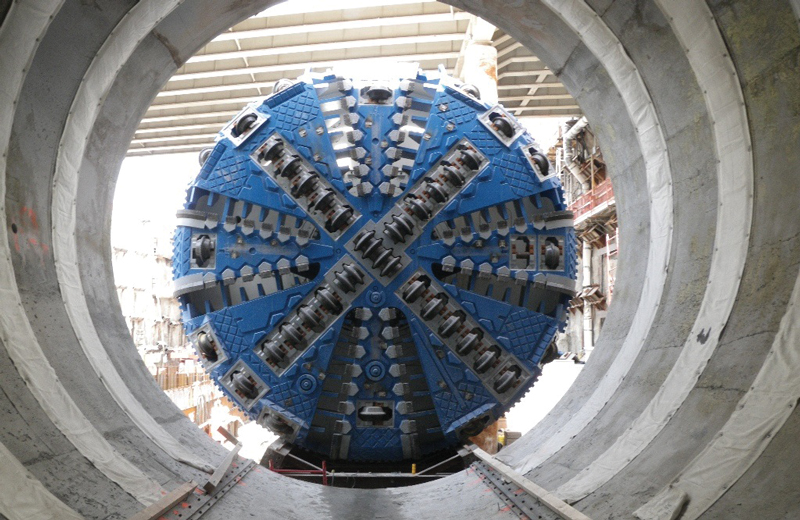
Figure 1. Pressurized tunnel boring machine.
Since subsurface conditions are a controlling factor for alignment selection, it is crucial to have an experienced geologist on the design team to review the existing subsurface information and evaluate the soil or rock formations during the initial phases of the project. Based on the location and depth of the selected alignment and the subsurface conditions, the geotechnical and structural designers will select the most appropriate type of excavation method and tunnel structure. Pressurized face Tunnel Boring Machines (TBMs), such as slurry and earth pressure balance machines, are often used for urban tunneling through soil to control ground deformations, prevent groundwater inflow, and minimize the risk of damage to adjacent buildings and utilities (Figure 1).
However, other types of tunneling, such as mined drill-and-blast tunneling in rock, the sequential excavation method (SEM) in soft ground, or cut and cover excavations, are used in urban tunneling, typically for non-circular or large diameter openings or in the presence of poor subsurface conditions or obstruction constraints. For shallow vertical alignments, cut and cover could be the preferred method; however, it creates the most community disturbance. Cut and cover excavation design requires considerable interaction between geotechnical and structural engineers for designing the temporary supporting system (e.g., soldier pile, slurry wall, secant pile, sheet pile) and waterproofing design. Cut-and-cover construction also requires coordination with civil engineers to address maintenance of traffic issues.
Site Investigation (Below and Above Ground)
Developing a subsurface investigation program (including field and lab testing) is a critical part of the design process. The depths and locations of the borings must be selected strategically to capture as much variation in the soil and/or rock conditions as possible. Therefore, having an experienced geologist on the design team and having local experience with the in-situ soil and rock types are crucial factors in developing a successful subsurface investigation program. In addition, structural engineer input (e.g., shaft or cavern depths and diameters) is required in selecting borehole locations and depths.
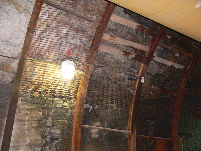
Figure 2. Shear zone in rock tunnel excavation.
It is necessary to have a thorough understanding of the geologic conditions before executing the design because unexpected ground conditions can cause significant delays and complications during construction. As an example, unanticipated highly fractured rock encountered during tunneling can cause issues for tunnel advancement and worker safety. Figure 2
shows a shear zone encountered during tunneling through a dolomitic rock formation, which delayed a project because the TBM grippers were not able to bear on competent rock to push the TBM forward. The figure shows the steel rings and mesh that had to be installed within the shear zone area to stabilize the tunnel heading, introducing extra cost and delay. The structural design of the final tunnel lining had to be revised because the internal diameter changed due to the deformed ground and intrusion of initial support elements. This delay and expense could have been avoided with more up-front costs on subsurface investigation.
In addition to subsurface conditions, the condition of existing structures along the tunnel alignment must be investigated. Structural engineers generally collect building and historical information and flag structures sensitive to settlement, which require special consideration, such as landmark or masonry buildings. The pre-construction inspection reports should include the types and depths of the foundations, structural materials and connections, and existing defects. The effect of tunnel construction on the existing structures must be evaluated during the design process, allowable movement thresholds determined, and strengthening or protection methods designed if required. Protection measures may include traditional underpinning or use of ground improvement methods. Protection of existing structures often influences the type of excavation support and bracing preloading requirements for cut-and-cover tunnel projects.
Design Collaboration
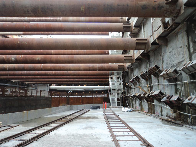
Figure 3. SOE system comprised of slurry walls, struts, and tieback anchors.
The design of cut and cover tunnel structures in urban areas requires close, multidisciplinary collaboration. Before excavation can begin, a complex network of buried utilities, such as gas and electric lines, sewers, telecommunications, and various other conduits, must be relocated or supported in place. Information regarding the location and type of utilities may be limited or nonexistent. The Support of Excavation (SOE) system sometimes needs to accommodate utilities that cannot be relocated – for example, by using jet grout columns as temporary walls in lieu of traditional elements such as sheeting or secant piles to allow a sewer to pass through the excavation. The SOE system itself must be designed to create the required architectural and structural space while minimizing impact to adjacent structures (Figure 3). Property limits can restrict space options and the method of SOE support. For example, when permission cannot be acquired to install temporary tieback anchors below an owner’s property, pipe struts may be used as an alternative means to support the SOE walls, but these restrict the temporary working space. Thus, design collaboration between civil engineers, electrical or telecommunications engineers, geotechnical engineers, and structural engineers is essential to satisfy the requirements of utility companies and other stakeholders and maintain the safety of the public.
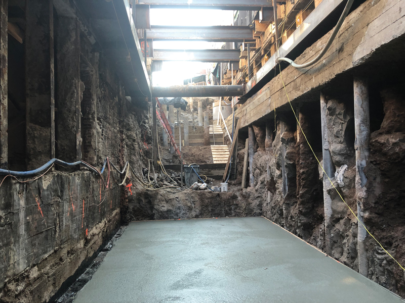
Figure 4. Urban excavation abutting existing tunnel (left) and other structures.
Rehabilitation and expansion of existing underground rail tunnel structures can require nonstandard support of excavation designs, requiring close coordination between structural and geotechnical engineers. Several projects the authors have been involved with have featured excavations above or adjacent to cut and cover tunnel boxes (Figure 4). Since it is often not feasible to install sheeting or piles on the tunnel roof, concrete button piers placed on the roof, above the tunnel walls, have been used successfully as SOE walls. These concrete button piers, cast-in-place using individual shoring boxes before mass excavation, act as soldier piles while minimizing damage to the existing structure. The button piers transfer additional load to the existing tunnel columns and walls.
In some cases, the tunnel box itself becomes part of the SOE system with struts bearing on the exterior wall of the tunnel box and transferring earth and surcharge loads induced by mass excavation to existing tunnel slabs. Some existing tunnel structures pre-date common structural shapes, such as wide flange beams, and require more detailed structural analysis. Historical drawings become critical references for allowable stress checks. The process of designing an appropriate SOE system, which can remain below the allowable stress increase of historical steel and cast-iron elements, requires close coordination between geotechnical and structural engineers.
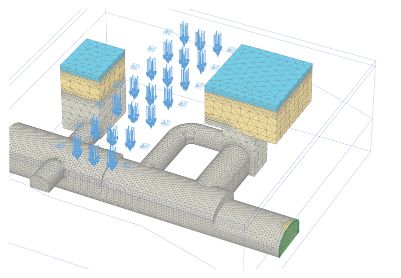
Figure 5. Numerical modeling of complex urban tunneling.
Mined tunneling (e.g., drill-and-blast through rock) also requires an iterative design process between geotechnical and structural engineers. The authors have worked on the development of many rock tunnels and caverns where the ground conditions and corresponding feasible excavation methods strongly influence the proposed geometry of final structures or architectural elements. New underground rail stations built in dense urban areas often require significant excavation beyond public platform areas. Ancillary shafts for ventilation or fire protection, electric substation vaults, passenger entrances, emergency egress tunnels, and cross passages between adjacent rail tunnels are all common elements of design in addition to multiple entrance tunnels, shafts, and connections to existing transit infrastructure. These multiple excavations often intersect or are adjacent to each other, which creates zones of increased stress within the rock mass. Geotechnical engineers perform rock mass stability analyses to determine if the architectural or structural configuration is feasible. During this iterative process, tunnels are sometimes relocated to allow for wider rock pillars to support overburden loads such as rock and soil cover, adjacent building loads, or other infrastructure (Figure 5). Rock mass quality and rock joint geometry will also dictate the type and extent of temporary excavation support.
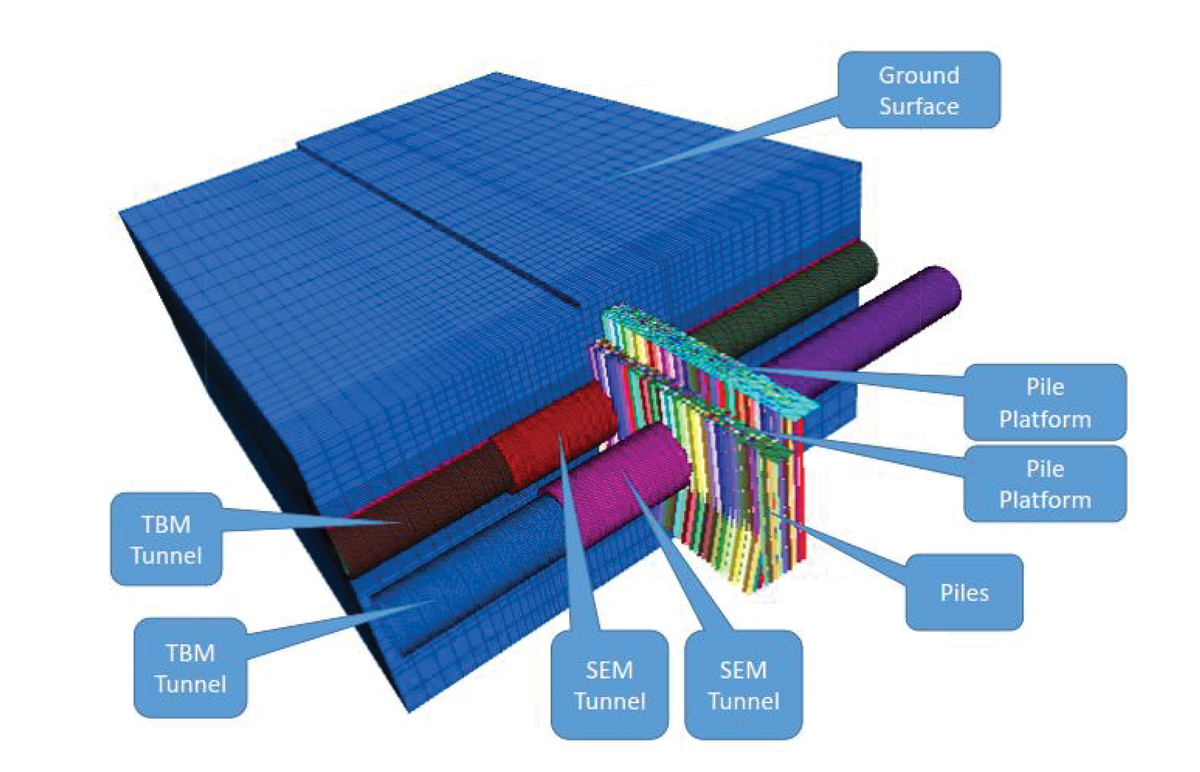
Figure 6. Numerical modeling evaluating the effect of tunneling through existing structures.
As discussed above, urban tunnel designers should also consider the effect of tunneling on existing structures. A recent project required an assessment of the effect of tunneling through lightly loaded timber piles that support an existing marine bulkhead. Due to the critical nature and complexity of the proposed tunnels and the relative locations to the existing bulkhead supported on timber piles, a three-dimensional numerical analysis was performed (Figure 6). The results of the analysis were used to estimate the ground surface settlement at different construction stages and to evaluate the impact on the existing vertical and battered piles. Cutting the existing piles would impose additional loading on the adjacent piles. This analysis was performed to evaluate the amount of the load that would be transferred to adjoining, un-cut piles, and evaluate the geotechnical and structural capacity of foundation.
Instrumentation and Monitoring
All underground excavation causes stress redistribution in the ground, which leads to ground deformation. Mitigating the associated risk is an essential factor during the design process. Although various choices can be made during the design process to reduce the risk of damage to adjacent structures, instrumentation monitoring of existing structures is a fundamental part of the construction process to provide a quantitative assessment of the tunneling operation and selected construction technology. The collected field measurements can also be used to refine the design analyses and modify construction procedures, if necessary.
Ground deformation monitoring is particularly crucial for shallow urban tunnel construction with a slurry or earth pressure balance shield. Empirical equations and numerical modeling, with analyses informed by precedent projects, are commonly used at the design phase to estimate the ground movement due to tunneling and for determining appropriate TBM face pressures. During construction, collected ground deformation data is reviewed against predicted values. This may result in previously performed analyses being modified and TBM operations parameters being adjusted. Collected ground deformation data can also be beneficial for any tunnel project that might be constructed in the future. On a recent project, field data collected in the mid-20th century was used to calibrate the analyses related to a new subaqueous tunnel at a nearby location.
Conclusion
Underground structures are in direct contact with natural ground materials, and that simple fact makes tunnel design a multidisciplinary problem. The subsurface conditions and the sizes and types of tunnels change from project to project, but one factor is constant: urban tunnel design and construction requires knowledgeable and experienced geotechnical engineers, structural engineers, systems engineers, geologists, and other disciplines to deliver a project successfully. Overcoming each challenge and providing the ideal solution as urban environments densify necessitates seamless communication and collaboration between multiple engineering disciplines. Individuals with different backgrounds and specialties must work together, collaboratively, to develop a project that meets clients’ expectations and offers the greatest added benefit to communities and society.■