
Transportation tunnel design and construction requires accepting the inherent uncertainty associated with subsurface conditions that can be characterized but never truly known. This article follows the geotechnical arc of a typical tunnel project from explorations and testing, to engineering analysis, supporting the selection of tunnel excavation methods, characterizing ground behavior, developing parameters for liner design, and estimating surface settlements and effects on adjacent structures. It provides examples from completed projects to highlight the risk and mitigation methods associated with underground construction.
Explorations and Testing
The elements of the geotechnical exploration program will vary based on the design phase, whether it is existing tunnel rehabilitation or new tunnel construction, whether it is a soil, rock, or soil and rock tunnel, and the anticipated complexity of the subsurface conditions. Typical steps for both existing and new tunnels include: 1) reviewing available data and 2) designing and implementing an exploration and testing program. The exploration program should be developed collaboratively with the design team and the owner to obtain both the parameters required for the design and to address identified types and areas of risk and uncertainty.
Existing Tunnels
The goal of the exploration program for existing lined tunnels is to understand the liner parameters and the anticipated loads. The program is designed to answer questions like: Can the existing liner accommodate new loads over or adjacent to the tunnel? Can the existing loads be accommodated if the liner is notched to improve tunnel clearance? How will the ground behave if portions of the tunnel liner are removed?
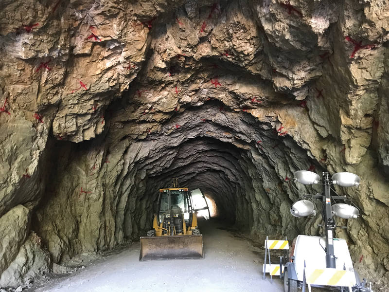
Unlined rock tunnel, subsequently supported with rock bolts and shotcrete to address rockfall risk.
For existing unlined tunnels, the exploration program focus is the required rock mass parameters for design. The program is designed to answer questions like: Will additional support be needed for tunnel enlargement? Can the tunnel accommodate changes in loading? What ground support or liner types are required to address a change in tunnel use?
The first exploration step should include reviewing existing geotechnical reports, design drawings, as-built drawings, and construction records or notes. Information on construction problems or the tunnel performance during use could help identify areas requiring additional analysis.
The second step is fieldwork to confirm the liner condition and configuration and understand the ground behind the liner. Even when design drawings and construction records are available, some confirmation explorations may be warranted. Where data is not available or there is a reason to suspect that the tunnel was not constructed in accordance with project plans, the field exploration effort will be greater.
Liner explorations could include probe holes drilled to estimate the liner thickness, concrete core samples for strength testing and identifying reinforcement, geophysical methods to identify the liner thickness and steel reinforcement, and condition mapping to identify liner distress areas.
Some of these same methods can be used to assess conditions behind the liner. Probe holes and geophysical methods can be used to characterize voids and the distance to competent rock. Specialized rock core drilling, such as used on the Cape Creek Tunnel near Florence, Oregon, can be performed from within the tunnel to obtain samples of the liner and soil or rock. The results of these explorations were used to confirm the presence of voids and collect samples that were used and tested to identify appropriate grouting methods, existing liner stability, and new liner design parameters.
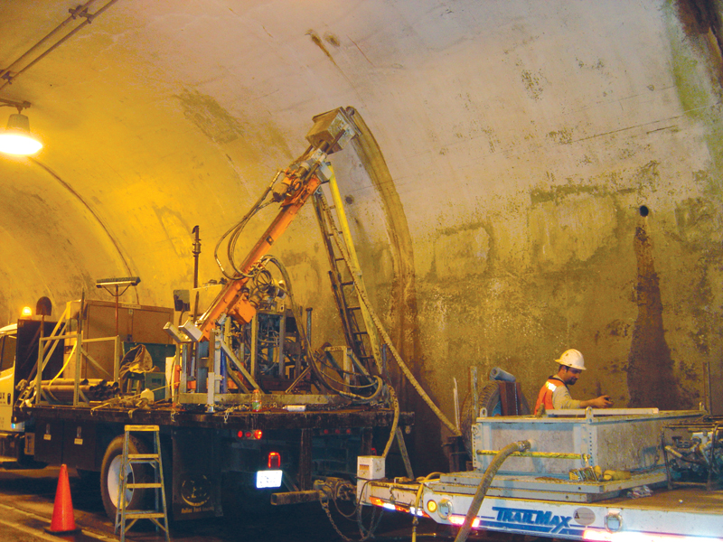
Specialized rock coring equipment for explorations within an existing tunnel.
The frequency and spacing of these explorations will depend on the anticipated liner and ground condition variability. The Owner’s risk tolerance for differing site condition claims during construction can also inform the frequency and spacing.
Existing stable, unlined rock tunnels provide an unparallel opportunity to map the geologic structure and characterize the rock mass. Sampling for testing rock strength or characterizing joint infilling may be needed for the final design.
Plotting all the data, including construction data, on the same tunnel map can be useful for identifying patterns and correlations. For example, there may be a correlation between identified overbreak or collapse areas during original construction and current liner distress areas. Alternatively, mitigation during original construction may have addressed the area of concern sufficiently such that no additional work will be required.
New Tunnels
Exploration program guidelines for new tunnels are available, including the AASHTO Manual on Subsurface Investigations published in 1998. The program for new tunnels is designed to answer questions like: What are the spatial distributions of soil and rock types and groundwater conditions? What are the design soil, rock, and groundwater parameters? What is the anticipated ground behavior? Are difficult conditions like abrasive ground, obstructions, or noxious/combustible gas present?
For transportation tunnels, the program is typically phased. For example, on the Beacon Hill Tunnel project in Seattle, Washington, only three explorations were performed along the approximate one-mile-long corridor to help select a preferred route. Once the alignment was selected, four additional explorations and related testing were performed to fill data gaps at the portal locations and improve the designers’ understanding of the subsurface conditions. A third exploration phase reduced the spacing between borings to about 300 feet and focused on the critical mined station excavation, the landslide hazard areas at the portals, and the Interstate 5 undercrossing. An approximately 150-foot-deep test shaft, telescoping down in diameter from 16 feet to 10 feet at a depth of 100 feet, was constructed during the final design phase to provide additional information on soil properties and ground behavior, and to provide the opportunity to bidders to observe in situ soil conditions. More expensive testing methods, such as aquifer pumping tests and test shafts, are commonly not completed until final design. The exploration and testing quantity and sequencing can also vary based on whether the project will be design-bid-build or design-build.
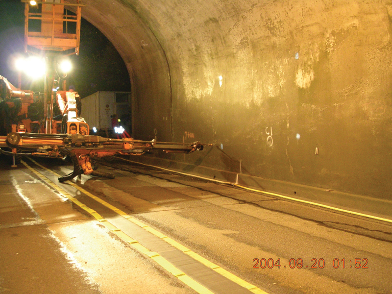
Drilling holes in an existing liner to fill with lightweight grout, for voids identified during the exploration program.
For soil tunnels, sonic core drilling to obtain nearly continuous soil cores is increasing in popularity. Mud rotary or hollow stem auger borings and penetration testing are still useful, particularly for characterizing conditions at portal or shaft locations. Reliance solely on penetration test samples may still be suitable in geographic areas with a history of successful tunnel construction and relatively homogeneous ground. Testing could include soil classification, unit weight, soil strength, deformation parameters, modulus, hydraulic conductivity, abrasion, x-ray diffraction, cobble or boulder strength, corrosion parameters, and combustible or noxious gas.
For rock tunnels, the exploration program would likely include vertical and angled rock core drilling, downhole testing to identify discontinuity spacing and orientation, permeability tests, and rock core tests. These tests could include unit weight, rock strength, modulus, durability, petrographic analysis, x-ray diffraction, abrasivity, and drillability parameters. Rock outcrop mapping, for rock mass parameters and to develop subsurface profiles, is also common. Geophysical testing to characterize the depth of soil overburden at portals and shafts may also be appropriate. For the 24-foot-wide, 3,100-foot-long Wheeler Gulch Tunnel in Colorado, where the geologic conditions could largely be interpreted from outcrop mapping and helicopter access was required, only a single rock core boring was performed.
The exploration and test results are used to characterize the ground type distribution; characterize ground behavior; develop engineering design parameters for structures and liners; and, develop baseline parameters to assist potential contractors with understanding the geotechnical risks.
Analysis for Existing Tunnels
Work on existing tunnels discussed in this article falls into one of three major categories, 1) lining a previously unlined tunnel, 2) partial liner removal, and 3) liner replacement. The parameters used in design and analysis will vary depending on the work being performed.
Liner Design
For existing unlined rock tunnels, a common working assumption is that the tunnel is statically stable, and the liner design will primarily need to support future loads. These future loads could include seismic, groundwater, or the development of additional rock load associated with weathering. Shear or weathered zones and loose rock blocks that cannot be safely removed may require additional support. The geotechnical engineer’s role on these projects is usually focused on estimating the potential additional groundwater and rock load and identifying likely reinforcement and liner types. For the Fishhook Tunnel in Idaho, the design incorporated differing permanent ground support requirements to address the differing long-term support requirements at the portals, where shear zones were present, and the remaining portions of the tunnel.
For existing liner notching or modification, numerical analysis is commonly required to accommodate the design of the irregular liner geometry resulting from the notching. The numerical analysis will require assumptions regarding the original methods used to excavate and temporarily support the ground to develop an estimate of the current load. The results may indicate that voids behind the liners need to be filled to reestablish the ground-liner interaction.
For liner replacement, understanding the ground behavior when the existing liner is removed is critical for determining the need for ground improvement or presupport. For example, on the Cape Creek Tunnel project, a combination of permeation grouting, void filling grouting, and drilled steel reinforcement was used to pre-support the ground during liner removal. The replacement liner design methods are the same as those discussed later for new tunnels.
Analysis for New Tunnels
Method Selection
The tunneling method selection could be the contractor’s responsibility or could be predetermined by the Owner and Owner’s engineer based on permitting limitations or project-specific requirements. The geotechnical data and analysis performed during design are used to help determine the appropriate excavation method. A partial list of methods that could be considered, depending on the anticipated subsurface conditions, includes: slurry pressure balance tunnel boring machine (TBM), earth pressure balance TBM, gripper TBM, open-face TBM, sequential excavation method (SEM), boom-mounted, milling excavator (roadheader), and drill-and-blast. Required cross-sectional shape and tunnel length, available work area, local contractor experience and availability, and project schedule can also influence the excavation method selected. The Sound Transit E330 Tunnel in Bellevue, Washington, is an example of where the project schedule and ability to take advantage of a non-circular cross-section led to the selection of SEM as the preferred method of construction.
Liner Design
The initial and final liner selection will depend on the subsurface conditions and also on the method selected. The shielded soil tunnels are commonly initially supported with precast concrete segmental liners followed by a cast-in-place final liner. SEM initial liners are usually a combination of shotcrete and lattice girders with other SEM toolbox items like grouting or presupport. The final liner is commonly shotcrete. Other methods, such as roadheader, drill-and-blast, or gripper TBM tunnels, could be initially supported with items such as spot or pattern bolts, mesh, and steel sets and wood lagging.
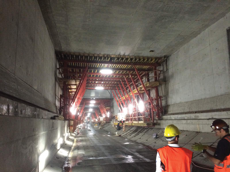
Final cast-in-place liner being installed within an initial, gasketed, pre-cast, concrete segmental liner.
The Federal Highway Administration’s Technical Manual for Design and Construction of Road Tunnels – Civil Elements provides design considerations and procedures for the common liner types used for transportation tunnels.
Settlement
The tunneling-induced ground movement magnitude can be the result of the Contractor’s selected means and methods. However, some ground movement is almost inevitable as a result of changing the stress in the ground during construction and the elastic response of the ground. In other words, assuming “zero settlement” is not practical. The estimation of settlement can vary from using empirical relationships between an assumed volume loss, soil type, tunnel diameter, and depth to a three-dimensional numerical analysis which accounts for anticipated soil and groundwater parameters, the state of stress in the ground before construction, and all of the subsequent construction steps. The effort is often directly related to the risk of ground-movement-induced damage. Where the tunnel is deep, has a relatively small diameter, and predominately single-story wood-framed structures are present over the alignment, the empirical analysis may be sufficient. The empirical analysis can also be used as a screening tool to identify buildings or structures that could require additional analysis. On the Alaskan Way Viaduct Replacement project in Seattle, Washington, the empirical analysis was used to estimate the settlement. Relationships between settlement, angular distortion, and damage were used to identify buildings and structures for additional analysis. For selected structures, such as the pile-supported Viaduct, numerical analysis was performed to estimate the potential settlement and damage as well as evaluate potential mitigation methods.
Conclusion
Geotechnical input for tunnel projects will vary depending on whether the work is being done for an existing tunnel or proposed tunnel, and whether the tunnel is in soil or rock. While relatively standardized approaches are available for analyzing new tunnels and new liners, modifications to existing tunnels can require significantly more analysis to address uncertainty and non-standard liner geometries parametrically. The effort and requirements to estimate settlement-induced damage can also vary widely from a quick empirical-based analysis to screening structures for potential damage to an in-depth soil-structure interaction analysis.■