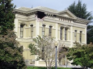
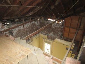
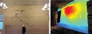
At 3:20 AM, August 24, 2014, the Napa County Historic Courthouse was severely damaged in the magnitude 6.0 South Napa Earthquake, which induced nearby ground motion readings indicating spectral accelerations ranging from 0.4g to 1.7g for low period structures. Most obviously, the top of the south east corner at the front of the building (east face), along with its attached dental cornice, collapsed outward to the sidewalk below (Figure 1). The Initial review also revealed a partial collapse of the exterior brick wall on the north elevation. At one corner of the building, the top two to three feet of brick wall fell inward, collapsing the ceiling framing above the jury room (Figure 2). There was significant additional damage throughout the exterior and interior masonry walls and the building frequently appeared in news coverage as a prominent downtown public building affected by the Napa Earthquake. The Courthouse was subsequently red-tagged by the City of Napa (the building was deemed unsafe for occupancy or entry, except as authorized by the local building Authority Having Jurisdiction per Applied Technology Council, ATC 20-1), beginning the long process to assess the damage, repair, and reoccupy the historic structure.
History
The Napa County Historic Courthouse was constructed in 1878, with an estimated $51,000 construction cost equivalent to approximately $1.3 million in 2019 dollars. It was added to the National Register of Historic Places in 1992. Before this building was built, two previous courthouse buildings existed on the same site. The original building was a prefabricated structure shipped to the city by barge in 1851. Just five years later, in 1856, the original building was replaced with a site-built courthouse that was ultimately deemed unsafe due to settlement and wall cracking. In 1874, construction began on the current courthouse, which has been serving the local community for over 140 years.
The current courthouse architectural design was provided by the Newsome Brothers, who also designed the Napa Opera House and the William Carson Residence in Eureka, with the assistance of local architect Ira Gilcrest. The Courthouse, along with the Hall of Records and Administrative Annex, occupies a city block bounded by 2nd, 3rd, Coombs, and Brown Streets in downtown Napa. The land for the Courthouse site was donated for use by City founder Nathan Coombs. As part of the original construction, a two-story jail was constructed west of the courthouse with a small access corridor between the two buildings.
In 1918, the Hall of Records building was constructed adjacent to the jail on the west end of the block. When the jail was demolished in 1977, a new Administrative Annex was built as infill between the Hall of Records and the Historic Courthouse to create a single-occupancy space. While the 1977 infill project is seismically separate from the Historic Courthouse, several large openings reinforced with concrete frames were added to the west wall of the Courthouse building, and multiple smaller openings were either added or infilled to accommodate new circulation patterns in the combined space. Additionally, in 1977, a seismic retrofit of the Historic Courthouse was performed with concrete pilasters added in the north and south exterior walls and the interior hallway corridor walls, and out-of-plane wall anchorage hardware was installed throughout. In 2003, a tenant improvement to the court clerk’s office added an approximately 25-foot-long concrete infill shear wall between the first and second floors along the north corridor wall.
The Courthouse is a 15,000-square-foot, two-story, unreinforced brick masonry building with wood-framed floors, ceiling, and roof. The original construction included an octagonal bell tower with an onion dome roof that was damaged in the 1906 San Francisco Earthquake and eventually removed in the early 1930s. The roof framing consists of straight sheathing over 2x rafters and site-built, large rough-sawn timber trusses, while the ceiling framing below consists of conventional 2x framing. Roof and ceiling framing both span between perimeter and corridor bearing walls. The floor consists of assorted finishes over straight sheathing with rough-sawn 3×12 joists.
ZFA’s longstanding relationship with Napa County and direct involvement with the Historic Courthouse since 2006 offered familiarization and knowledge of the building invaluable to the process after the earthquake and repair solutions beyond.
Damage from 2014 Earthquake
ZFA was brought in as part of a team tasked with completing the Courthouse repair after the building was shored under a prior contract with a separate design team. Before beginning repair design and drawings, ZFA completed an extensive damage documentation effort to reveal and illustrate the level of damage to the client and the insurance company’s peer review engineer for confirmation of required repair scope.
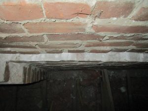
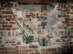
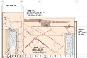
In addition to obvious partial collapses, the building sustained significant damage at the second-floor level and along the front of the building. The front (east) façade, consisting of a series of reentrant corners stepping out horizontally towards the front entrance, experienced significant corner damage throughout. Observed damage included: diagonal cracking of walls leading to in-plane and out-of-plane horizontal wall displacements up to three inches (Figure 3); multiple localized or partial collapses of brick walls (Figure 4); failure of both the original out-of-plane government roof-to-wall anchors and the 1977 retrofit wall anchorage; and significant non-structural damage, including broken sprinkler lines that caused additional water damage.
The out-of-plane wall anchorage included failures of both the original government anchors (approximately 8-inch-diameter iron plate on the far face of the brick wall anchorage by a flat plate through the wall to the wood framing beyond) and the 1977 retrofit adhesive anchors. Observed failures included: wythe pullout, retrofit anchor adhesive bond failure, buckling of 2x diagonal braces, net tension rupture of 2x braces, and bolted connection failures in 2x members. With few exceptions, out-of-plane wall anchorage failures were concentrated at the roof/attic level.
Documenting the Damage
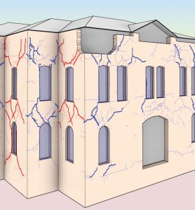
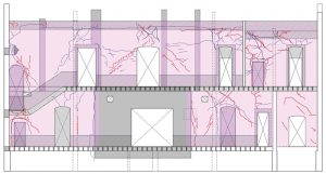
In lieu of traditional damage documentation methods, in which reviews are completed on a room-by-room basis, generally looking at a wall from one side at a time, ZFA employed a wholistic 3-D approach. Detailed and scaled field observations of damage on both sides of walls (cracks, deflections, displacement of wythes, localized collapses, and failures in out-of-plane wall anchorage), as-built conditions differing from the original construction, and 1977 reconfiguration documents were combined with original construction documents to create a 3-D BIM model. All observed wall cracks were modeled with different color and weight 3-D model lines. Blue lines indicated cracks occurring on the north or east faces, while red indicated cracking on the south or west faces of walls. Model line weights were also varied to depict crack size thresholds. Wall profiles were edited to show localized collapsed areas and voids.
A 3-D exterior site scan was completed shortly after the earthquake for use in shoring design, and an internal 3-D scan of each room was completed during the damage documentation phase. The resulting data point cloud was linked into the BIM model to verify dimensional assumptions and aid in building deflection review and assessment. Sections were cut through the walls with the point cloud to illustrate out-of-plane wall displacements and verify wall thicknesses that were otherwise difficult to identify solely through field observations. The 3-D scans were also used to generate “heat maps” (Figure 5) showing relative out-of-plane displacements in a colorized gradation to augment the documentation drawings.
Using the damage documentation 3-D BIM model (Figure 6), two-story full-length wall elevations and 3-D views clearly illustrated crack patterns on both sides of walls (Figures 7 and 8). Using this whole-building approach to documenting the damage, significant two-story diagonal crack patterns were revealed that extended through wall faces, providing valuable insight into the global building behavior and resulting damage extent from the earthquake.
Assessing the Damage
FEMA 306, Evaluation of Earthquake Damaged Concrete and Masonry Wall Buildings, was used to classify observed failure modes and provide an estimated loss of strength for each wall pier along each wall line. Typical failure patterns included wall-pier rocking, in-plane flexural cracking, and out-of-plane flexural cracking. Additionally, significant corner damage was observed due to the reentrant corner configuration along the eastern front façade, resulting in the partial collapse of two walls at the roof. In addition to the more common damage patterns documented in FEMA 306, weak pier/spandrel joint damage patterns were also observed at exterior corners and reentrant corners. The combination of the field observations, 3-D BIM modeling, and FEMA 306 analysis created a summary of the damage documentation that was used to develop a conceptual repair approach for review and discussion with the insurance company’s peer review engineer.
Because of the historic materials and construction techniques, 140 years of use and modification, and the wide range of damage throughout, a single repair option was not appropriate. The repair concept, therefore, used a combination of traditional brick repair methods, repointing, grout injection, and localized areas of brick rebuild along the western portion of the building. However, the more heavily damaged eastern portion and corridor walls required a creative repair approach to save the historic fabric of the building and provide improved structural performance.
This repair approach included the use of Fabric-Reinforced Cementitious Matrix (FRCM), one of the first applications in California, and wall reconstruction with specially-detailed CMU construction to replace the walls in the areas of heaviest damage.
A more detailed review of the various repair and rehabilitation techniques utilized will appear as a future article in STRUCTURE.■
Project Team
Owner: County of Napa
Structural Engineer: ZFA Structural Engineers
Historic Preservation Architect: TreanorHL
Architect: TLCD Architecture
Owner’s Rep: AECOM
General Contractor: Alten Construction

