
International WELL Building Institute (IWBI) defines WELL as “Buildings and Communities that help people thrive.” Where LEED focuses on the performance of a building, WELL focuses on the performance of the occupants. WELL Building Certification was developed through a medically proven research matrix that focuses on the health and wellness of building occupants. WELLv1 is based on seven concepts (Air, Water, Nourishment, Light, Fitness, Comfort, and Mind) with over 100 features (www.wellcertified.com).
In late 2018, Little, a national architecture and engineering firm, moved its Charlotte, NC, office into a newly constructed building in the heart of the city’s uptown. In addition to being a flexible, adaptable environment pursuing both LEED and WELL certification at a Silver level (targeted to be one of the first WELL spaces in Charlotte), the interior upfit focuses on vibrancy, energy, rawness, complexity, and, most of all, connectivity. Helping to drive all of these factors through the 14th, 15th, and 16th floors occupied by the firm, Little incorporated an open, internal staircase that acts as a focal point – an architectural center of gravity.
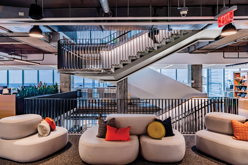
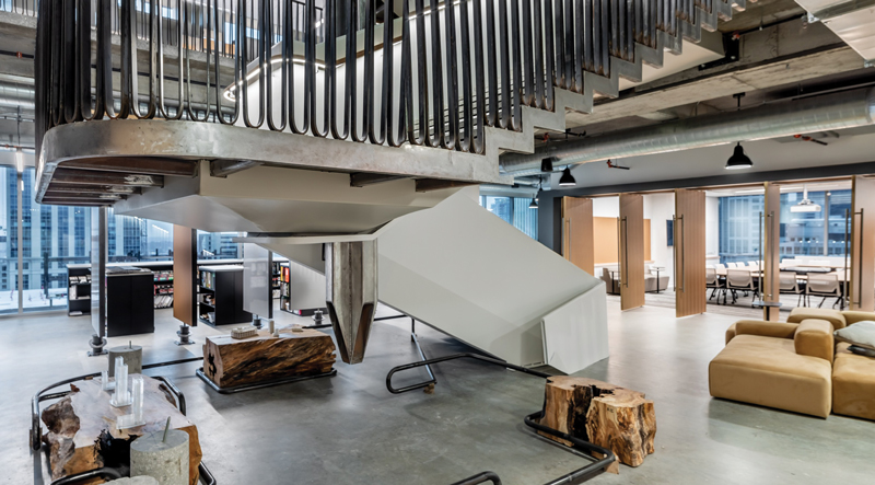
View from Level 15.
This monumental centerpiece, however, is not a typical connecting stair. Little used its engineering, design, and architectural expertise to create a structure that not only facilitates impromptu meetings and idea exchange but provides an unexpected visual statement – starting at the top.
Aligning Architectural and Engineering Goals
Instead of being traditionally anchored and reinforced at the lower level, which would disturb existing tenants on the 13th floor below, this 30,000-pound stair hangs from a four-pronged, structural mast on the underside of the building’s 17th floor.
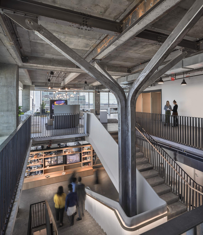
Four-pronged hanger at Level 16.
Ensuring structural reliability was a challenge for the design team. The team knew it did not want to add significant strengthening to the existing building structure. Using the existing building as it was originally designed reduces the carbon footprint of the renovation while also making it more cost-effective. With the stair connecting three of Little’s floors, the team was able to remove the mildly reinforced concrete slab and a 21-inch mildly reinforced concrete beam at two levels, totaling 56,000 pounds of concrete – more weight than the actual stair. The team distributed the load of the stair to the underside of the 17th-floor beams with bolted steel channels to support the stair and designed for the live loads required by code.
The team initially evaluated a straight hanger to suspend the stair from the 17th floor. However, this type of hanger pushed almost the entire load to the 17th floor, which would have required strengthening the existing structure. Instead, after several iterations, the team crafted a four-pronged structural mast to transfer some of the load, due to flexibility of the prongs, to the 16th and 15th floors, allowing the existing structure to adequately carry the appropriate load. Approximately 55 percent of the dead and live loads are carried by the 17th floor, while the 16th and 15th floors support the remainder of the load transferred from the inside HSS14x4 stringers (see Figure 1 and further explanation below).
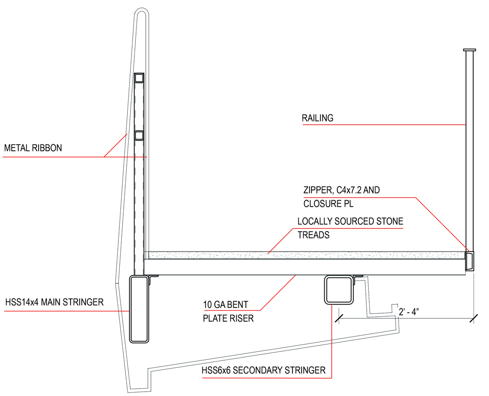
Figure 1. Monumental stair section.
Every project attempts to combine architectural intent with engineering design but, in this unique case, the two aligned perfectly. The architects introduced a concept of a flaring mast to symbolize a ‘spark’ (one of Little’s core values is to ‘spark’ a spirit of excitement and discovery). This introduced the structural flexibility needed to better share the stair load between multiple floors. Four 2¼-inch-diameter pins accomplish the mast connection to the 17th floor. This connection is utilized to eliminate the transfer of any moment into the existing structure while complimenting the rawness of the design.
Creating the Stair Opening
Beyond the mast concept, the design team had to evaluate the location of the staircase carefully. The existing cast-in-place concrete structure of the building consists of 48-inch-wide post-tensioned (PT) girders in both directions between columns supporting mildly reinforced beams at approximately 11-foot centers and a one-way 5-inch-thick mildly reinforced concrete slab. The location of the 17-foot by 22-foot floor opening for the stair was selected to not only be directly in front of the lobby elevators but also between four PT girders to avoid cutting any post-tensioned cables. Also, the placement eliminated requirements for reinforcing the existing slab which was then cantilevered past the nearest girder. The maximum cantilever of the concrete slabs and beams cut to form the stair opening on the 15th and 16th floors was 2 feet, 7 inches from the edge of an existing PT girder. The existing slab was checked for this cantilever and reinforcement was deemed not necessary. One existing 12-inch-wide beam was removed from each slab for a length of 22 feet. The remaining beam on either side of the stair slab opening was checked to verify stresses and deflections were within allowable code requirements. The PT girders were checked with the removal of the concrete slab to verify they were not overstressed and still met ACI serviceability for uncracked members.
Building the Stair Structure
The main stair structure was designed to give the impression that the stair is “floating.” Two HSS10x6 outriggers are cantilevered from the steel mast at each level supporting each HSS14x4 stringer, and an HSS14x4 outrigger is cantilevered from the mast to support the landing. The main HSS14x4 stringer runs along the inside edge of the stair directly under the inside railing and is supported by the 15th and 16th floors as well as the HSS10x6 outriggers at the intermediate landings, framed back to the center mast. A secondary HSS6x6 stringer runs along the stair approximately 2 feet, 4 inches from the outside edge of the stair (Figure 2). The architects requested the edge of the stair treads be exposed steel, which was termed the ‘zipper.’ The 10 gage stair treads cantilever 2 feet, 4 inches past this secondary stringer and support the C4 zipper, which in turn supports the outside railing.
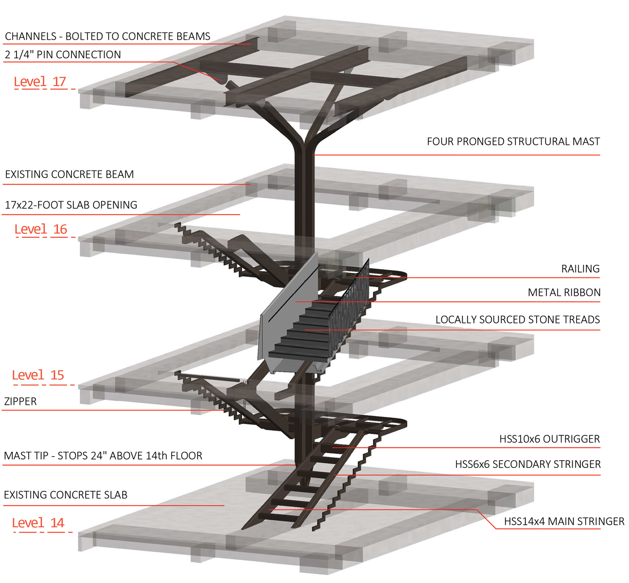
Figure 2. Monumental stair isometric.
The design of the stair also included checking step live loading with live load only on half the stair, as well as only on the landings, to verify stresses and movement. Differential deflections of the 15th– and 16th-floor structural members were also checked as altering these movements changed the amount of load supported by the 17th floor.
Executing the Installation
Even with diligent planning from both the engineering and design team, the stair execution did not come without its challenges. One obstacle was the limited size of the building freight elevator and getting materials to the 16th floor. The solution – the stair was constructed at the fabricator’s (CM Steel) shop and then cut into 42 pieces to be delivered and re-connected on site. Once in the space, the stair was pieced back together using full penetration welds. The construction sequence took advantage of the existing floor by installing the hanger framework on the underside of the 17th floor before cutting the new holes in levels 16 and 15.
The team also had to pay careful attention to not damaging rebar and PT cables while adding the connections to the 17th floor and attaching the stringers to the 15th and 16th floors (bolted to the PT girders). All reinforcement and PT cables were located by the use of X-ray and ground-penetrating radar (GPR) before drilling.
While the structural integrity of the stair was important, so was its architectural design. A winding ribbon of structural steel that creates a finished backbone rendered in white is a stark contrast to the rawness of the steel that it threads together. All exposed steel was left to patina for several months in the field and was later rubbed with a protectant bee’s wax. Bee’s wax was selected to meet the WELL requirements for the space.
Base of the stair.
The apparent hand of the craftsperson was also integral, and the materials used were critical in how the stair would invite users. In this case, the more ‘raw,’ the better. Bolted connections, welds, bends, and cuts became the narrative to the inherent beauty of material, in how they look, feel, and sound. The visible welds were lightly ground smooth to keep with the rawness. The stair railing surrounding the stairway was envisioned by the design team to mimic the shading of architectural sketches.
This three-story monumental stair, suspended in the center of Little’s space, is sensible and understandable yet impressive in unexpected ways. Since physical activity is essential to our health, this feature, luring employees away from the elevator and encouraging movement, has been a key feature in supporting the environment’s pursuit of WELL Silver Certification.■