Innovative Approaches to Vertical Expansion
To Rebuild or Reposition? That is the fundamental question every developer must address when acquiring a site with existing conditions. In New York City, a place known for its ephemeral urban fabric and innovative high-rise buildings, large developments often lean towards a tabula rasa (clean slate) for ease of construction and maximum flexibility. Cove Property Group, however, had other plans when they acquired a drab eight-story commercial building on 34th St and 9th Ave in Manhattan. The existing 1960s-era cast-in-place concrete building would receive seventeen additional floors, encompassing 300,000 square feet, in the form of a sleek steel office tower. When its transformation is complete, Hudson Commons will be a 26-floor, LEED Platinum Class A property accommodating 700,000 square feet of rentable office space (Figure 1).
Hudson Commons was conceived by Cove Property Group. The architect of this visionary renovation and addition is Kohn Pederson Fox Associates (KPF) with WSP serving as the engineer of record. Mueser Rutledge Consulting Engineers (MRCE) served as the geotechnical consultant. The construction manager is Pavarini McGovern (PMG).
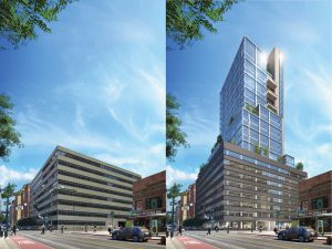
Figure 1. Before and after renderings of the Hudson Commons renovation. Courtesy of Neoscape, Inc. 2017.
Project Description
Hudson Commons is situated in the heart of Manhattan’s west side. The area has seen an expansive transformation in recent years, most notably the 14-acre Hudson Yards megaproject just to the west. As a direct neighbor of Penn Station to the east, the site is tightly woven into the urban fabric and infrastructure of New York City.
The existing 423,000 square-foot cast-in-place structure was initially designed as a warehouse and built in 1962. The structure is comprised of two-way concrete slabs on a 24- by 28-foot grid with drop panels, “mushroom” capitals, and a masonry core providing lateral stability. The low, massive building is representative of the period. Early site investigations showed that the robust structure was in excellent structural shape.
The expressive vertical expansion adds 17 floors of steel construction rising to 421 feet, bringing the total rentable area to 700,000 square feet. The addition takes the form of a sleek modern office tower inherently amalgamated to the bold Hudson Yards development rising just beyond. The subtle renovation of the original building, which includes a new wrap-around brick façade and curtain wall, keeps the project grounded in the context of the neighborhood and its 1960s roots.
Accomplishing the vision developed by Cove and KPF required WSP to face several unique challenges which would inspire highly innovative structural solutions. Indeed, the existing cast-in-place columns and footings required sizeable retrofits for the gravity loads of the new tower above, and the existing roof slab required extensive retrofitting to accommodate a landscaped park. The most invasive feature, however, was the addition of a new reinforced concrete core linking existing and new construction to provide lateral stability for the new taller building. Adding to the complexity of the upgrades was the combined decision of the client and the CM team for a shoring-free demolition of a 125- by 25-foot area throughout the existing building to accommodate the new core.
Foundation System
The geotechnical composition of the site and the existing foundation elements presented an interesting engineering challenge. While the existing structure was bearing on the good-quality substrate typical of Midtown Manhattan, the bearing capacity ranged from 20 to 40 ton/ft2, and there was a steep drop off through the site. Furthermore, the constraints of working within the confines of an existing structure were immediately evident, particularly for the use of deep foundation elements and the associated equipment.
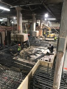
The new reinforced concrete core is supported by a new 48- to 72-inch-thick mat foundation bearing directly on sound bedrock (Figure 2). With the core walls in-line with existing columns, consideration of existing column foundations added another layer of complexity. While some column foundations were narrow piers reaching the bedrock, a few columns were supported by larger pile caps. The latter were treated as breaks in the mat foundation with cold joints only. The small footprint of the new core translated to large overturning moments which were addressed by providing 45 600-kip anchors socketed 45 feet into rock. MRCE specified 450-ton micropiles socketed 15 feet into sound bedrock to achieve the required load demand. Three types of foundation retrofits were developed:
- Piers-to-rock encapsulating and tied into existing piers-to-rock,
- New caisson caps articulating existing piers-to-rock, and
- Enlarged caisson caps articulating existing pile caps.
Gravity System
Originally designed as a moderately-loaded warehouse, the existing structure is inherently robust. The reprogrammed office building affords a load “credit” from the reduced demand. Even with this credit, there was insufficient capacity to accommodate 17 additional floors. Large spans (up to 48 feet) in the office tower, to achieve expansive column-free areas, amplified the demands at the base of the building where more load goes to fewer columns. Conversely, a smaller number of columns had the benefit of an overall reduction in the reinforcing steel for the project.
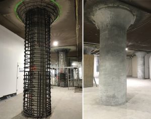
The solution implemented by WSP was the retrofitting of existing concrete columns employing new reinforced concrete “jackets.” Before arriving at this solution, and as with any project involving existing structures, the first task was the assessment of existing conditions and a study of available construction documents. Although some original drawings were available, core samples were extracted from various locations to determine the in-situ compressive strength of concrete. Also, WSP provided 3-D laser scanning services for the entire structure which yielded an accurate representation of as-built column dimensions and locations, the latter being critical to tie in the tower grid above. To minimize any potential compatibility effects, concrete strength for the retrofitting jackets matched the one determined through the coring campaign (approximately 5,000 psi).
Continuity of reinforcement was critical to maintaining a consistent load path. GPR scanning was performed at each column allowing WSP to map and coordinate locations for holes to be drilled for reinforcement to pass through the existing slabs. Large diameter (#14 bars) and high-strength (Gr 75) reinforcement were utilized to maintain jacket thicknesses under 12 inches, resulting in 60-inch-maximum-diameter columns. Column capitals were removed to achieve the desired reinforcement continuity; however, they were rebuilt during the cast operation to maintain the original aesthetic (Figure 3).
The forming and casting of circular columns in the building’s constrained environment was a costly and troublesome prospect. Shotcrete was used for columns and capitals to circumvent this difficulty. Concrete was placed and compacted/consolidated at the same time due to the force with which the shotcrete is sprayed. A skilled technician hand trowels the last layer, leaving the final product indistinguishable from traditional methods. Typically used to line tunnels and swimming pools, this application by the construction team proved invaluable and was a genuinely innovative and unique feature of Hudson Commons.
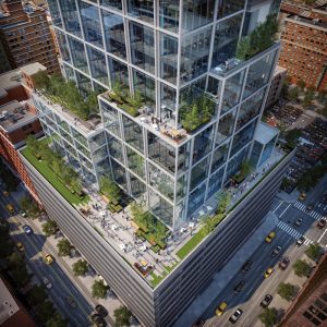
Figure 4. Rendering of the green amenity space on the roof of the existing building. Courtesy of Neoscape, Inc. 2017.
WSP faced another interesting challenge in the conversion of the existing roof to a lush landscaped amenity area, which is one of the numerous green spaces throughout the building (Figure 4). The existing structure had limited load capacity as it was designed initially as an unoccupied roof. The first solution involved a layer of CFRP under the slab with a new concrete topping slab. As the landscape design evolved to include up to 4 feet of soil in some locations, a critical threshold was reached making the CFRP-based solution unfeasible (per the provisions of ACI Committee 440 in the Guide for the Design and Construction of Externally Bonded FRP Systems for Strengthening Concrete Structures).
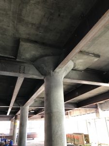
WSP worked closely with PMG to determine the most cost-effective approach, and the final structural solution was a secondary support system of steel beams installed under the existing slab in the green areas. New steel members were designed as non-composite sections to eliminate the need to perforate the roof for stud installation. Clips were installed along the length of the beams to prevent lateral-torsional buckling (Figure 5).
Lateral System
Hudson Commons required a full upgrade of its lateral load-carrying system to provide stability of the existing structure and the new tower above. WSP worked closely with KPF, whose architectural design included a new circulation and mechanical core eccentrically placed along the north side of the property to maximize the rentable area. One of the most notable features of the Hudson Commons core, however, is its prominence in the architectural expression as it rises above the existing building. The new spine of the building reads as such, using exposed architectural concrete to celebrate the material in a tribute to the historic architecture of the neighborhood.
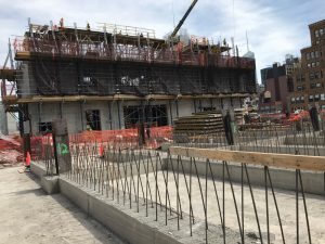
The new reinforced concrete core runs from foundation to the top of the building and is comprised of 10,000-psi concrete shear walls ranging from 12 to 24 inches in thickness (Figure 6). To counteract the torsional effects of the eccentric core, WSP envisioned a box-like configuration wrapping the entire mechanical and circulation program. In this closed-box system, the core is placed along existing column lines, and the existing columns create breaks in the shear walls analyzed by considering individual piers at the base building. While this might not be ideal from a structural perspective, the benefit of this approach was the absence of link beams in the base building, which allowed maximum flexibility with regards to routing services out of the core. Above the existing roof, the walls are connected through reinforced concrete link beams to provide adequate lateral stiffness. Three-dimensional finite element analysis software was used to model both the existing and new structure allowing for an optimized and efficient structural design.
The two main challenges of the new core system were constructability and the desire by Cove and PMG for a shoring-free demolition for the new core (Figure 7), given that shoring systems are costly and may stifle construction progress. The unique solution implemented by WSP was to reinforce the existing concrete slab with steel members around the perimeter of the area to be demolished. Steel members were installed above and below the slab following the bending moment demand. Top steel members were removed after casting the core walls. Steel members below the slab were fitted with studs to trigger composite action and remained as a permanent bracket connecting the new core walls with the existing slab. This innovative solution resulted in significant savings in terms of both cost and schedule.
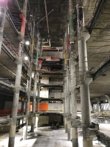
Figure 7. Shoring-free slab demolition for the core with temporary steel above the slab and permanent steel below the slab.
A Vertical Expansion Showcase
Hudson Commons presented an interesting challenge. Shotcrete column encasements and retrofitting of various foundation elements allowed the addition of 17 floors and about 300,000 square feet of rentable area to the existing structure. Strengthening of the existing roof to accommodate its conversion to a lush amenity space is a standout. KPF’s design celebrates this essential element of the structure by leaving the new spine exposed as it reaches skyward from the base. Careful attention to constructability and sequencing contributed significantly to the project’s success.
Hudson Commons demonstrates unique and innovative solutions to overcome the limitations of adaptive reuse and showcases the possibilities of large scale vertical expansion. With developers and cities alike striving towards more sustainable solutions to expansion, the relevance of such projects is rapidly accelerating. Hudson Commons topped out in late 2018 and was scheduled to be tenant-ready by the end of summer 2019.■

