
The New Science Center (NSC) at Amherst College anchors the eastern edge of the bucolic hilltop campus in Amherst, Massachusetts. From overall organization to the finest detail, the design of the NSC achieves transparency and interaction at every level. The surrounding landscape seamlessly meets the transparent glass façade of the Commons, blurring the edges of the central living room and creating a gathering space that feels like an extension of the outdoors.
The glass façade of the Commons is a structural silicone glazed curtain wall system comprised of triple-glazed insulating units and an automated shading system which controls the glare and the overall lighting levels. The curtain wall is hung in tension from a steel roof structure cantilevered up to forty feet over the Commons below. The structure supporting the curtain wall is comprised of a paired steel plate assembly and steel tee profile which acts as the vertical mullion for the system. The approach to hang the system and design the structure as an assemblage of components, rather than a larger single member, resulted in maximized transparency and transmission of daylight as it filters through the members to the interior.
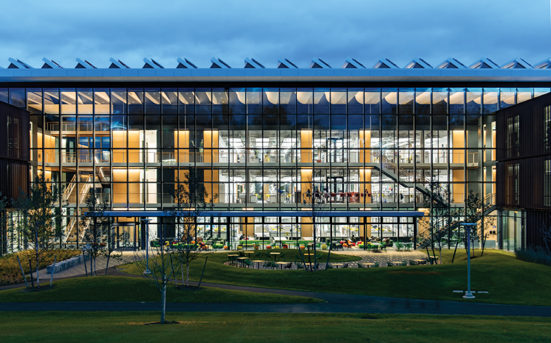
Amherst College’s New Science Center enlivens the sciences on campus by allowing the community to see the work being done. Courtesy of Chuck Choi Architectural Photography.
The building’s primary unifying feature is the distinctive roof which covers the multi-story, glass-enclosed Commons and provides a quiet visual datum for the undulating Pelham Hills beyond. The roof performs many functions simultaneously: it provides both natural and artificial light, its photovoltaic panels generate electricity, and its shape and materials afford acoustic control, all while radiantly heating and cooling the Commons. The steel roof structure, concealed within curvilinear glass fiber reinforced gypsum ceiling panels, is cantilevered from the exposed concrete structure of the lab wings over the Commons, which in turn suspends the glass curtain wall.
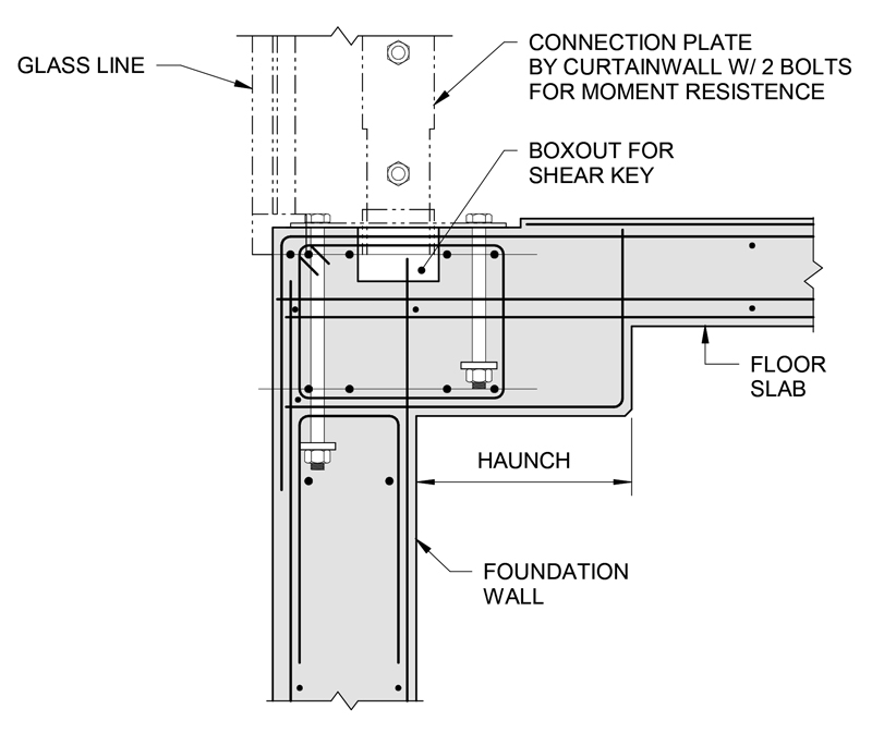
Structural detail at the base of the glass wall and the connection to the concrete wall and slab.
In realizing the architectural vision of the Commons space, a structural scheme needed to be developed that would accommodate the multi-story, column-free space and would evince the feel of a living room serving the whole campus. By hanging the glass wall from the roof structure, the wall mullions would be in tension and thus would require smaller sections to resist the design loads. Concurrent with being in tension due to the self-weight of the steel and glass, the paired plate mullions of the glass wall are subjected to bending forces from the wind and seismic loads acting laterally. The tensile stress in the paired plate mullions is analogous to a pre-tension of the steel so that, in bending conditions, the mullions remain in permanent net tension, thus negating the need for stability bracing. The base of the mullions are connected through two vertically slotted holes which allows the bending moment to be resisted – and resolved to lateral loads into the concrete slabs – while preventing any vertical load forcing the mullions into compression.
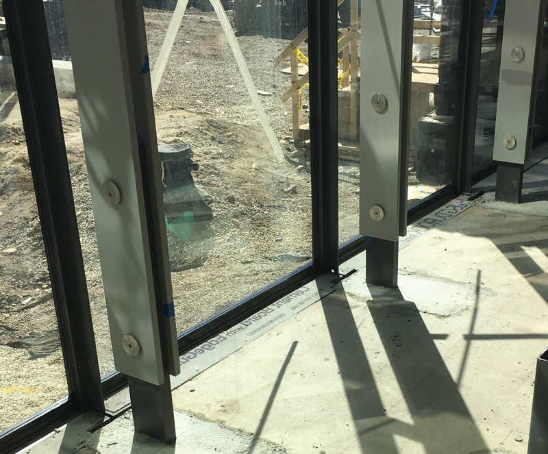
View of the erected steel paired plate mullions and two-bolt connection at the base of the glass wall.
The structural system of the NSC is cast-in-place concrete throughout. However, the roof structure spanning over the Commons necessitated a steel frame to sustain the weight of the glass wall concurrently with cantilevering over the column-free Commons space. The columns supporting the glass wall are nearly 40 feet removed from the curtain wall, supporting a load of nearly 10,000 pounds per mullion in addition to the dead, snow, wind, and seismic loads.
The roof frame is comprised of cantilevered beams reaching from 32 to 40 feet from its nearest support, each aligned with a curtain wall mullion assembly. Near the free end of each cantilever is the connection of the curtain wall; each connection sustains up to 10 kips. The cantilevers are anchored to the tops of the concrete columns in the lab wing. Due to the programmatic need for an open lab environment, it was infeasible to have columns spaced at the same 5-foot-3-inch-rhythm of the roof steel. As a result, some of the cantilever steel roof beams were supported not directly by columns, but by girders spanning between the columns.
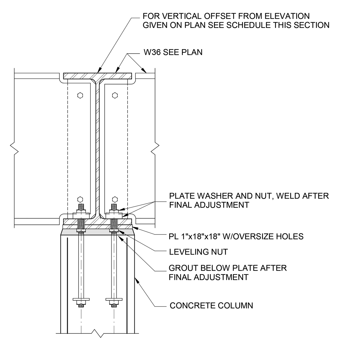
Structural detail of the cantilevered W36 roof beams with leveling nuts for adjustability throughout glass installation.
Each roof cantilever supported variable amounts of load, adding a layer of complexity to the already-variable support conditions: cantilevers supporting the full 70-foot-high glass are flanked on each side – where the pavilions interact with the glass wall – by cantilevers supporting loads for only a 10-foot height of glass. In some instances, beams supporting the highest and lowest loads were immediately next to one another; the relative stiffness of adjacent cantilevers needed to be tailored on a one-by-one basis so that two conditions were met:
- The top of the glass wall (i.e., the underside of steel) was at a constant elevation after the glass was hung.
- No two adjacent cantilevers deflected more than ¼ inch differentially under transient loads (wind, seismic, snow).
Because cantilevers holding different loads and consisting of varying supports will lead to different structural deflections, the two conditions noted above needed to address both the initial position of the cantilevers and the in-situ movements of the cantilevers.
Initial Position – Adjustability
W36 steel beams were selected for the cantilevers in all instances to maintain consistent steel elevations, both at the top of steel for a flat roof and the bottom of steel for a consistent datum for the glass wall; this also allowed for a consistent length of glass wall mullions. Due to the varying stiffness of the cantilevers and the changing magnitude of the applied loads, leveling nuts were implemented where the cantilevers were anchored to columns.
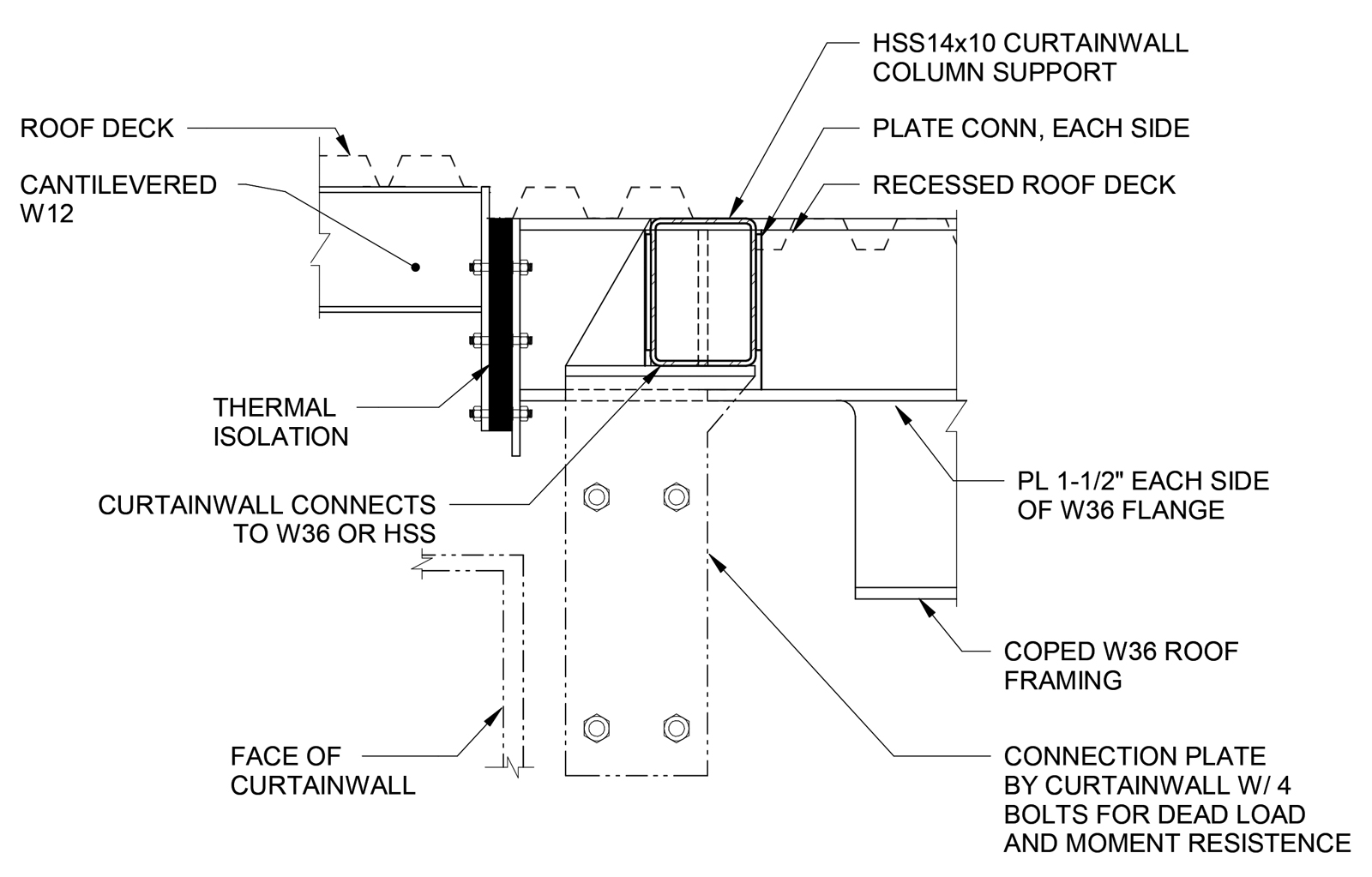
Structural detail at the head of the glass wall and the connection to the cantilever beams.
These nuts, sometimes as far as 40 feet from the glass wall, allowed very fine adjustments to the initial position of the steel cantilevers by turning the nuts as much or as little as needed; a small adjustment in the leveling nut would result in a comparatively large repositioning of the cantilever at the glass wall position. In this manner, each cantilever was able to be set at a pre-determined elevation before loading the steel with the glass wall. Selecting the proper elevation to set the cantilevers required that the Glass Design-Assist Contractor supply LeMessurier with the loads of the glass wall at each cantilever so that deflections could be predicted. This would allow the steel to deflect to the datum elevation once the entire glass wall was suspended from the roof steel. The predictions of steel deflection were determined via a full finite element model of the roof frame, applying the glass reactions supplied by Novum Structures.
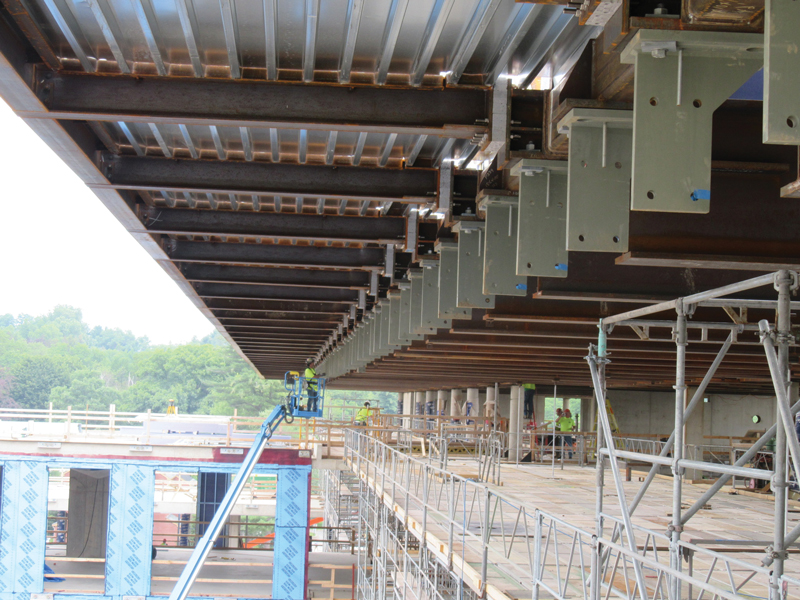
View of the erected roof framing and curtain wall connection plates at the top of the wall.
In-Situ Deflection Control
Once the glass wall was hung from the roof steel, achieving a consistent horizontal datum across the roof, the differential deflection of adjacent cantilevers needed to be controlled to limit the stress placed on the caulking between adjacent panes of glass. By querying the roof finite element model, the section properties of the cantilevers were adjusted to result in deflection characteristics across the entire roof such that no two adjacent cantilevers deflected by more than ¼ inch due to transient loads. This effort involved increasing the section properties of some W36s (including custom built-up shapes) to decreasing the section properties of others and allow normalization of deflections at each cantilever location.
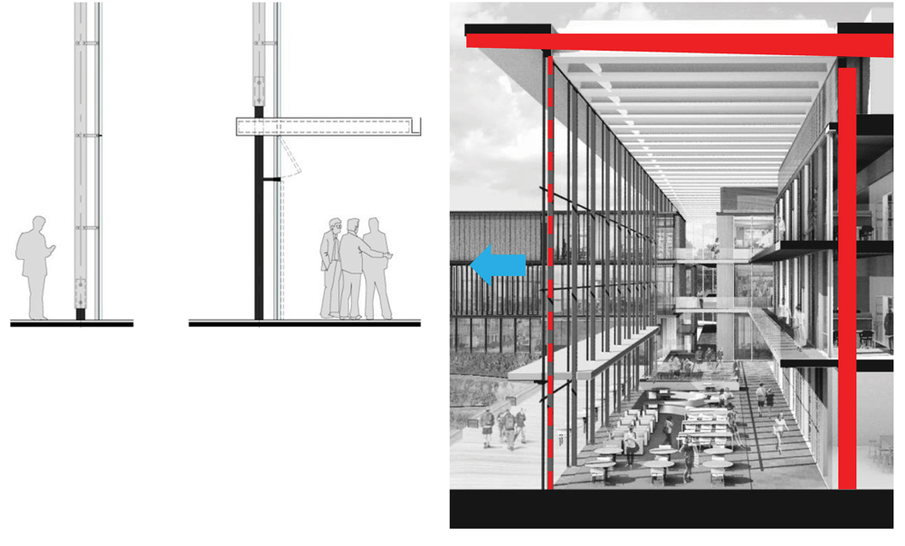
Schematic section at Commons showing the framing geometry of the column (right),
glass wall (left) and the roof cantilevers (top).
Installation followed the careful planning and selection of the cantilevers. Barr & Barr engaged Structures Derek to erect the structural steel with the task of setting each piece at its designated elevation. To achieve this, surveys were conducted frequently to provide continuous feedback about the position of the steel defining the datum at the top of the glass. As the cantilevers were tied together with secondary framing and roof deck, final adjustments were made to the steel before installing the glass. Once the roof was in its final connected condition, adjustments at one leveling nut resulted in a proportional effect on cantilevers on either side of the adjusted location. Surveys were conducted periodically through the installation of glass, and corresponding adjustments were made at the leveling nuts so that, at the end of glass installation, the steel had come into alignment across the entire length of the roof, precisely as planned.
Faced with an aging science center unable to accommodate today’s technologies, equipment, and pedagogies, Amherst sought a new, forward-looking building that would create an open learning environment for the entire campus community for the next 100 years. By creating a Commons space that was welcoming, the desired effect of a living room had been brought to life inside the New Science Center. The resulting glass wall, with its perfectly vertical and horizontal datum lines, underscored the close coordination of the entire project team. It was through this meticulous craft in design and construction that the driving forces of layered transparency and academic connectivity were achieved, and the campus fundamentally transformed for the future.■
Project Team
Owner: Amherst College, Amherst, MA
Structural Engineer: LeMessurier, Boston, MA
Architect: Payette, Boston, MA
Construction Manager: Barr & Barr, New York, NY
Structural Steel Contractor: Structures Derek, Sainte-Marie, Quebec, Canada
Glass Design-Assist Consultant: Studio NYL, Boulder, CO
Glass Design-Assist Contractor: Novum Structures Menomonee Falls, WI