
The Broadway Bridge, connecting Little Rock and North Little Rock in Arkansas, was replaced in 2016 using an incentivized bidding process to minimize the duration of the bridge closure. Each bidding Contractor was required to add to their base bid a cost of $80,000 per day for each day the bridge would be closed. Since the new bridge is located along the same alignment as the original bridge, the ideal sequence of completing new construction and switching traffic was not possible. Based on the winning bid proposed by Massman Construction Co., the duration of roadway closure was limited to 180 days starting the day the existing bridge was closed. The roadway closure duration guarantee was part of Massman’s $98.4M contract price. As such, the planning and sequencing of construction activities were critical to accomplish both bridge demolition and new bridge construction within the allotted time limit.
New Arch Spans
The highlight of the new bridge was two 440-foot network-tied-arch spans over the Arkansas River. The tight project schedule dictated that these spans would be erected before the bridge closure and at a location away from the final alignment so that they could be installed as quickly as possible following removal of the existing bridge. Also, the final height of the bridge over the river is significant which added to the complexity of replacing these spans.
Arch span prior to closure.
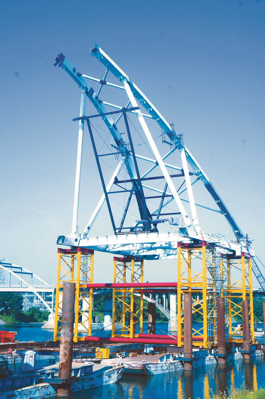
The new tied arch spans were each constructed on a system of custom falsework towers supported on barges immediately downstream of the existing bridge. The barge system for each arch span consisted of four 35-foot x 195-foot deck barges connected together. Fabricated steel towers were utilized to support each steel arch span on the barges for erection.
Following arch erection, the spans were individually floated into position and installed on the permanent bearings. The height of the towers and the height of steel erection above the barges varied between 56 and 68 feet, based on the final bridge profile. The height of the system, including the falsework towers and steel grillage system, allowed for span float-in at nearly the final elevation and the span lowering was accomplished using only barge flotation and ballasting (no hydraulic jacks were required).
Falsework Towers and Barge System
The towers were developed considering future use and constructed for modular assembly. The main column members were 24-inch x ½-inch round pipe members (ASTM A252 Gr. 3). Diagonal and “k-frame” angle bracing members were included in the tower modules for stability.
The steel towers were supported by a steel grillage system and reinforced connections within the existing barges. The supporting members of the system were connected into the frame of the barges to avoid concentrated load effects applied to the deck of the barges. Local reinforcing of the internal barge framing consisted of vertical column members, stiffeners, and bearing plates welded to the side and center longitudinal bulkhead plates.
Lateral stability of the barge system was a significant design consideration and was facilitated through the use of significant bracing between towers. The system was constructed to develop continuity and rigidity between individual barges to create a stable flotation system, forcing the set of four individual barge units to work together as a group.
Steel Erection
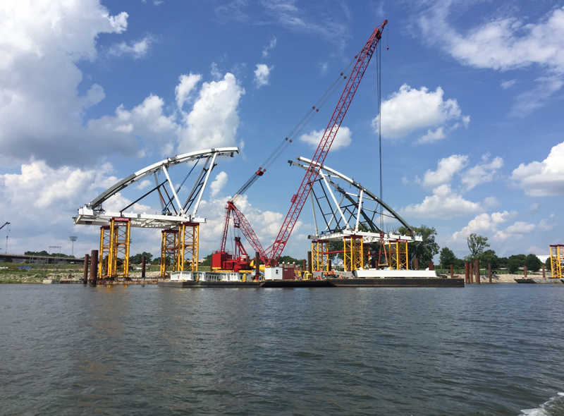
The large and heavy steel arch spans were assembled in field segments on the falsework towers. Massman Construction Co. used a large barge-supported ringer crane to do all steel erection, and the crane’s significant lifting capacity allowed for steel to be erected in large, pre-assembled segments. The first and most substantial segment to be erected was the end floor segment, with weight approximately 625,000 pounds. Each of the floor system field segments and arch structure field segments were pre-assembled on staging barges and subsequently lifted as units into position on the falsework towers.
Arch span during erection with adjustable temporary struts.
Each half-span was assembled independently on separate barge pairs including the steel tie girder segments, connected floor system, arch ribs, and associated bracing members. Large-diameter steel pipe struts with length and load adjustment capability temporarily supported the arch ribs. Temporary cables were utilized to support the floor system that briefly cantilevered from the falsework towers. The use of the axial compression struts and the temporary tension cables allowed for system position and member force adjustments during the erection process.
Following the independent assembly of each half-span, the supporting barges were moved together, and the span segments were joined by erecting the center deck field segments. This was a critical stage, as the complete span was supported temporarily on variable barge supports. Following placement of the center floor system segment, the center keystone arch segment was erected to close the tied-arch structure.
The temporary conditions during erection were carefully studied with a staged erection computer analysis using LUSAS Finite Element software. Results of the computer model included member forces, deflections, and reactions which were used for the design of the temporary support system, barge floatation analysis, and geometry controls. Temporary load demands for the arch structure were computed to confirm adequacy for each construction stage as a part of the erection engineering effort.
Hanger Installation and Tensioning
Hangers consist of two 2⅜-inch-diameter ASTM A586 strands at each permanent hanger location. Each cable is pin-connected to the arch and tie girder with an open “prolite socket” and pin provided by CBSI, Clodfelter Bridge and Structures International, Inc. The girder connection of the hanger is made using an adjustable rod. Detailed length calculations were required for each hanger to determine the fabrication lengths and geometry conditions during installation and tensioning. The geometry of the hanger connection details facilitated the need for a custom-designed and fabricated tensioning bracket which included tensioning bars, custom steel frames, and center-hole hydraulic jacks.
Original Bridge Demolition
Constructed in 1923, the original bridge was comprised of 37 cast-in-place concrete girder spans and five 200-foot concrete arch spans. In 1974, two of the concrete arch spans were replaced with a single 412-foot steel arch span. The entire existing structure had to be removed as a part of the project.
As noted, the bridge demolition was on the critical path, and swift completion was essential to the overall project success. Due to the project timing restrictions, the substructure units for the new bridge had been constructed under the existing bridge at the time the demolition operations were to be undertaken. The presence of the newly-constructed substructure complicated the operation and required detailed planning to avoid damaging these elements.
The concrete deck for all spans was removed using a team of excavators working together in a planned operation. The excavators started at the steel arch river span and worked toward the ends of the bridge, proceeding in opposite directions. The team of excavators also removed the spandrel columns for the concrete arch spans as a part of the deck removal process.
The multiple concrete arch spans and the single steel arch span were all removed using explosive demolition techniques. The explosive demolition operations were carefully planned in consideration of the stability of the temporarily-remaining structures as well as the safety of the nearby urban infrastructure. The stability of the spread-footing foundations on the existing bridge limited the load imbalance that could occur at the piers, so the explosive demolition sequence was planned based on these limitations.
A full demolition engineering study of the structure and proposed demolition techniques was completed to determine that the sequence of demolition would be feasible and the operations would be safe.
New Spans Float-In Operations
The weight of each assembled arch span was more than 4,000,000 pounds and had a center-of-gravity nearly 100 feet above the river, so the operation of transporting the span to its final location was critical. The travel distance from the erection location to the final bridge location was about 1200 feet. Since the travel distance was relatively short, winch lines were installed to assist multiple tug boats to pull and push each arch span into position. With the use of both the winch lines and tug boats, the barge-supported arches were slowly maneuvered into position without incident.
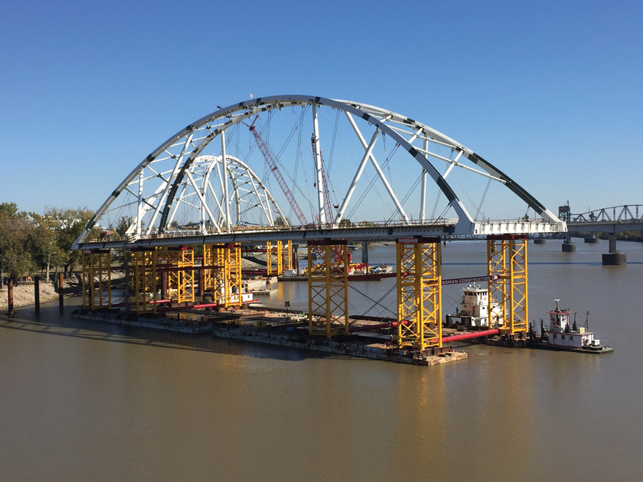
Span configuration for float-in operation.
Geometric restrictions were tight for the float-in operation due to the minimal clearance over preset bearings and the limited lowering distance available based on barge freeboard. Once in the final position, the barges were flooded with ballast water, effectively lowering the system to engage the permanent bearings. The float-in operations were successful – no significant geometric conflicts were encountered, and the spans were both successfully delivered to their final locations.
Final Construction Activities
Following the span float-in operations, the adjustable struts were removed and the remaining cables were installed and tensioned. The new concrete deck was then constructed in six separate pouring sequences. Final cable hanger forces were adjusted to achieve the intended deck geometry and bridge profile, and construction of the bridge was completed. This project successfully replaced the Broadway Bridge by pre-erecting two 440-foot tied arch spans to facilitate span placement within the short-duration road closure. The total duration of roadway closure was 152 days, which included the safe demolition and removal of the original existing bridge and complete reconstruction of the new bridge. Extensive planning and execution resulted in the safe and successful replacement of the bridge within the allotted timeframe.■
Project Team
Owner: Arkansas Department of Transportation
Design Engineer-of-Record: HNTB Corporation
General Contractor: Massman Construction Co.
Erection Engineer: Genesis Structures, Inc.
Analysis Software: LUSAS Bridge Plus Finite Element Software