
Part 4: Walls
This article is the fourth in a series on recommended reinforcement details for cast-in-place concrete construction. Parts 1, 2 and 3 ran in June, July, and August 2019 of STRUCTURE.
Concrete Cover
Concrete protection for reinforcement plays an essential role in the requirements of bar spacing and bar development. Reinforcing bars are placed in a concrete member with a minimum concrete cover to protect it from weather, fire, and other effects. Minimum cover requirements for nonprestressed, cast-in-place concrete construction are given in Table 20.6.1.3.1 of ACI 318-14, Building Code Requirements for Structural Concrete. For walls, the concrete cover is measured from the surface of the concrete to the outer edge of the layer of reinforcement closest to the wall surface.
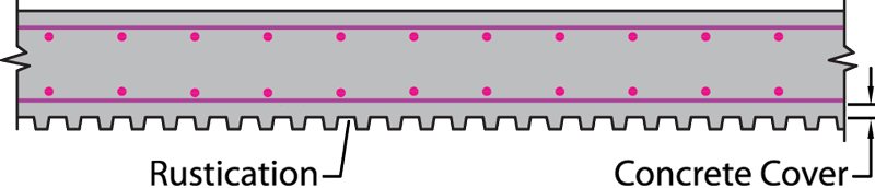
Figure 1. Rustication over entire length or height of a wall.
Where reveals or rustications run the entire length or height of a wall, the minimum required coverage to the reinforcing bars is indicated in Figure 1. A constant concrete cover is maintained from the inside of the reveal to the surface of the wall. Potential problems can occur where rustications are located in specific areas of a wall. It is evident from Figure 2a that the cover to the transverse reinforcement is smaller than that which is required. One solution is to offset the reinforcing bars in the localized area to maintain the required cover (Figure 2b). The detailing and placing of the reinforcement can become quite challenging if more than one area of rustication is required or if the rustication is located near an opening in a wall. A more viable solution is to treat the rustication area as an opening and provide an inner layer of reinforcement with the proper cover (Figure 2c).
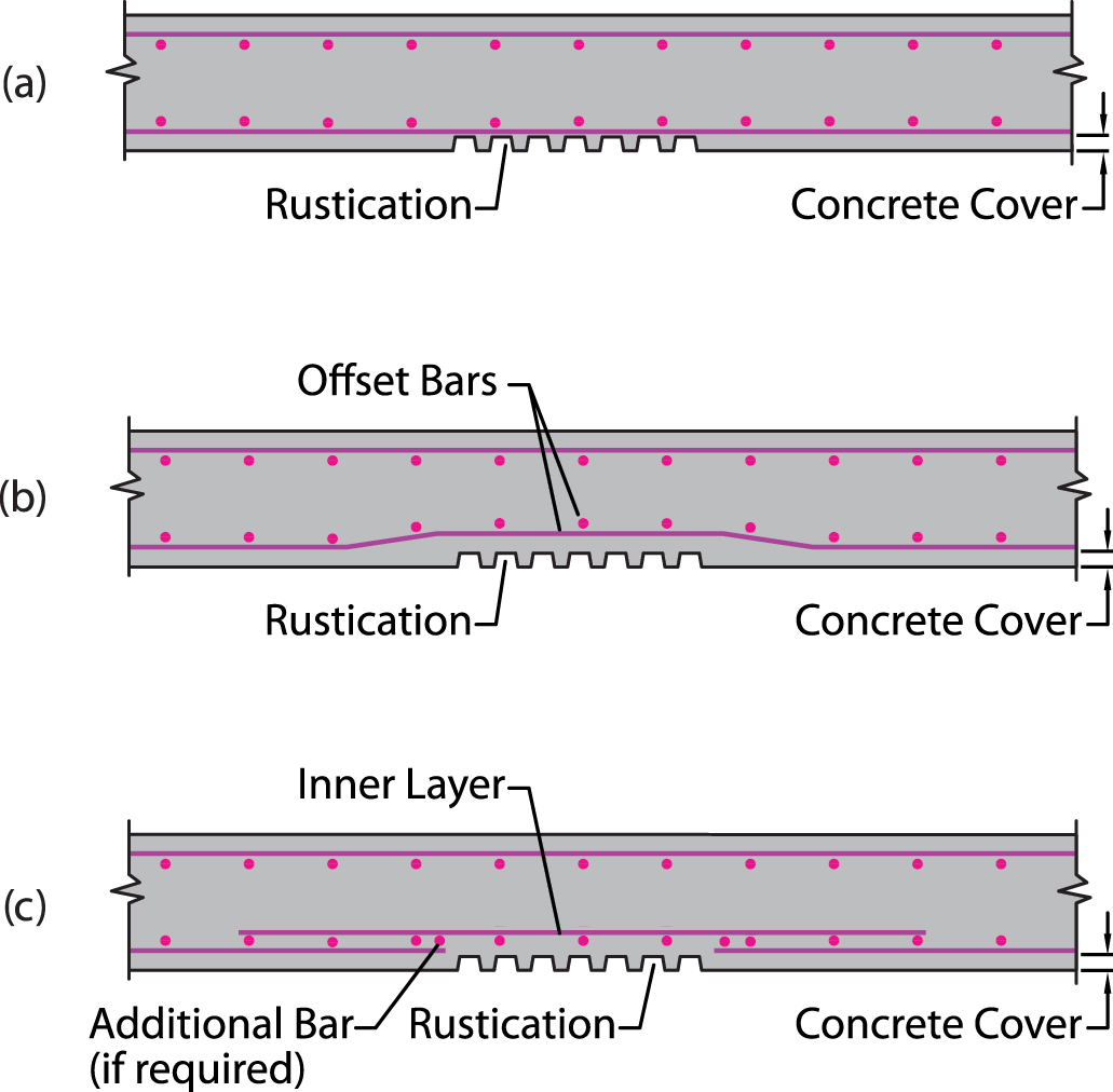
Figure 2. Rustication over a portion of a wall. a) Minimum concrete cover not provided; b) Offset Bars; c) Inner layer of bars.
This reinforcement should be developed beyond the rustication area in all directions.
Wall Openings
Inevitably, openings of various sizes and shapes for doors, windows, conduit, piping, and ductwork will need to be made in structural walls. Mechanical, plumbing, and electrical openings are usually located just below the slab but, in general, could occur anywhere. Additional reinforcement must be provided around the perimeter of wall openings, commonly referred to as trim bars, opening bars, or corners bars. Section 11.7.5 of ACI 318-14 requires that, for walls with one layer of reinforcement in both the longitudinal and transverse directions, at least one #5 bar must be provided around an opening. Similarly, at least two #5 bars are required around openings in walls that have two layers of reinforcement in both directions.
Longitudinal trim bars around the sides of an opening that run the full height of a wall and that get lap spliced with dowels protruding from the footing should be avoided. Detailing and placing full-height trim bars can be a problem because the exact locations of the wall openings may not be available at the time the concrete for the footing is placed; thus, the dowels may not be at the correct location.
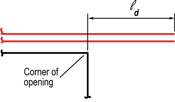
Figure 3. The preferred reference point for development length of trim bars.
The preferred reference point to measure the development length of trim bars is at the corner of the opening, as shown in Figure 3. This is an advantageous location for the detailer and placer because it is a fixed point. Measuring the embedment length from a longitudinal or transverse trim bar is frequently done, but the embedment length may wind up being too short if the perpendicular trim bars adjacent to the opening shift for whatever reason from their intended location (Figure 4).
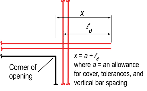
Figure 4. Development length of trim bars measured from perpendicular trim bars.
Wall Corners and Intersections
Reinforcement at wall corners and intersections need to be carefully detailed to avoid installation problems and more. Long transverse bars with hooks at one or both ends should be avoided because they are challenging to install. Wall bars are often assembled in curtains or mats that are lifted into position. Hooks complicate preassembly, transportation, storage, and handling of the curtains. Constructability is enhanced by providing straight horizontal bars that are lap-spliced together by separate bars; by doing so, adjacent curtains can be installed without interference. Also, the curtains can easily be adjusted to maintain proper concrete cover as the independent hooked bars used for the lap splices are tied in place. The costs associated with the extra reinforcing bars needed for the lap splices are far outweighed by the costs associated with the labor needed for increased handling and installation of the bars with hooks on the ends.
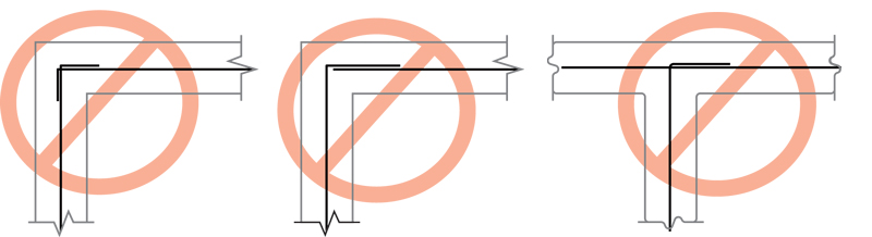
Figure 5. Wall corner and intersection details that should be avoided – single layers of transverse reinforcement.
Three examples of details at corners and intersections that should be avoided in walls with one layer of transverse reinforcement, because of the reasons noted above, are given in Figure 5. The preferred details are given in Figure 6, which show the separate hooked bars that are dowelled to the straight bars in the wall.
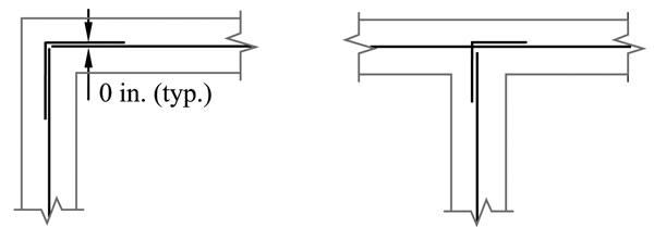
Figure 6. Preferred wall corner and intersection details – single layers of transverse reinforcement.
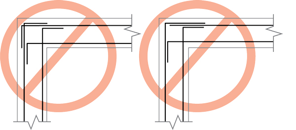
Figure 7. Wall corner details that should be avoided – double layers of transverse reinforcement.
The details shown in Figure 7 at the corners of walls, with two layers of transverse reinforcement with hooks on their ends, should be avoided because they make it difficult to use preassembled curtains of bars. Of the three arrangements illustrated in Figure 8, Figure 8a is common, but Figure 8b is preferred because the separate 90-degree hooked bars that are lap-spliced with the two preassembled double-bar curtains of transverse reinforcement is easy to construct. Figure 8c is also easy to construct for preassembled curtains, but it can only be used in walls that are thick enough to accommodate the width of the U bars (hairpins) at the ends that are lap spliced to the transverse reinforcement in the walls.
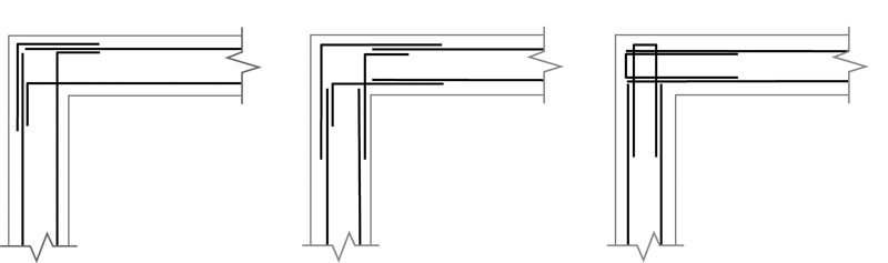
Figure 8. Preferred wall corner details – double layers of transverse reinforcement.
The detail in Figure 9 should be avoided at wall intersections for the reasons stated previously. The preferable layouts are shown in Figure 10. Once again, the layout in Figure 10b is only possible in relatively thick walls.
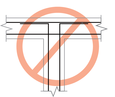
Figure 9. Wall intersection detail that should be avoided – double layers of transverse reinforcement.
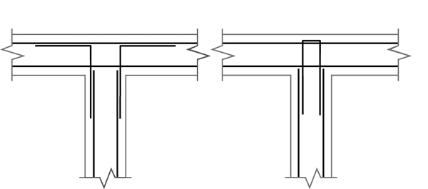
Figure 10. Preferred wall intersection details – double layers of transverse reinforcement.
Additional recommendations and guidelines for detailing reinforced concrete walls in buildings assigned to any Seismic Design Category can be found in the CRSI publications Design Guide for Economical Reinforced Concrete Structures and Design and Detailing of Low-Rise Reinforced Concrete Buildings.■
References
ACI (American Concrete Institute). 2014. Building Code Requirements for Structural Concrete and Commentary. ACI 318-14, Farmington Hills, Michigan.
CRSI (Concrete Reinforcing Steel Institute). 2016. Design Guide for Economical Reinforced Concrete Structures. Schaumburg, IL.
CRSI (Concrete Reinforcing Steel Institute). 2017. Design and Detailing of Low-Rise Reinforced Concrete Buildings. Schaumburg, IL.