
The Steel Joist Institute (SJI) defines a Joist Girder as “…a primary structural load-carrying member with an open web system designed as a simple span supporting equally spaced concentrated loads of a floor or roof system acting at the panel points of the member and utilizing hot-rolled or cold-formed steel.”
If the Joist Girder is not a simple span, or if the loading condition is anything other than concentrated panel point loads, the Specifying Professional must clearly indicate the loading (i.e., end moments, axial forces, and other required design information) on the construction documents.
The “Basic Connection” used by all Joist Girder Manufacturers for simple spans is one where the Joist Girder seat rests on the column cap, and the bottom chord angles slide between a stabilizer plate. The manufacturer designs the Joist Girder seat for the imposed vertical concentrated loads. The Basic Connection becomes a moment connection when the bottom chord of the Joist Girder is welded to the stabilizer plate. This connection has very limited moment capacity. Its strength is limited by bending stresses, induced in the top chord by load path eccentricities (Figure 1).
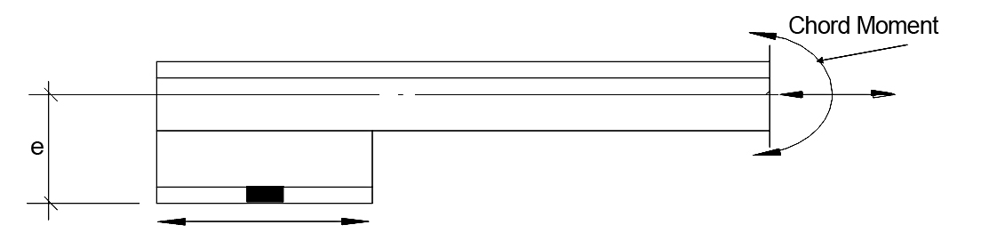
Figure 1. Chord bending.
The purpose of this article is to discuss moment connection design tools that are available from SJI at no cost to engineers and detailers. These tools can assist the design professional by making the design process more timely and complete. SJI provides six different spreadsheets to assist in the design of moment connections. Each can be used to calculate connection strength based on the necessary limit states. A reference manual is provided with each Spreadsheet, explaining the calculations. Each Spreadsheet provides for the design of a Joist Girder framing into one side or both sides of the column. The six connection Spreadsheets are:
- Connection to the Strong Axis of Wide Flange Columns
- Connection to the Strong Axis of Wide Flange Columns – Intermediate Levels
- Connection to the Weak Axis of Wide Flange Columns
- Connection to HSS Columns – Top Plate
- Connection to HSS Columns – Knife Plate
- Connection to Wide Flange Columns – Knife Plates
Although the Spreadsheets are specifically written for the design of moment connections, they can also be used for cases where Joist Girder additional top and bottom chord axial load transfer is required.
It is expected that the spreadsheet user is familiar with the SJI Specifications for Joist Girders (Standard Specification for K-Series, LH-Series, and DLH-Series Open Web Steel Joists and for Joist Girders, ANSI/SJI 100-2015) and the AISC Specifications (Specification for Structural Steel Buildings, ANSI/AISC 360-10). Before using the Spreadsheets, the user should perform a structural analysis to determine that the column has the available strength to resist the applied loads.
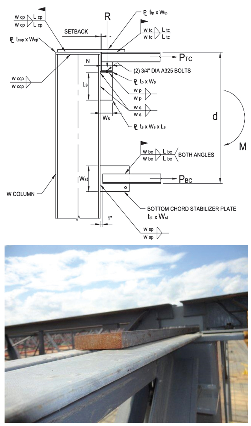
Figure 2. Joist girder moment connections to the strong axis of wide flange columns. Courtesy of Johnson & Burkholder, Engineers.
This article focuses on the Joist Girder Moment Connection to the Strong Axis of a Wide Flange Column (Figure 2) with additional information available in the reference manuals and spreadsheets. The other Spreadsheet tools follow a similar presentation. In this detail, the Joist Girder vertical reaction is supported by a stiffened seat welded to the column flange. If the Joist Girder is modeled as a truss, the chord forces are obtained directly from the model; however, if Joist Girders are modeled as beam elements, chord forces are determined by resolving end moments into force couples. Top chord force is transferred to the column by a top plate field welded to the chord and to the column cap plate. For Joist Girders framing to both sides of the column, the top plate is also used to transfer continuity forces from one Joist Girder to the other. Bottom chord force is transferred to the column via the stabilizer plates. Numerous limit states, which must be examined, are discussed below.
Top Chord Connection
The required top plate strength is determined from the axial force in the top chord (Pu = Mr/de); where Mr is the required end moment of the Joist Girder and de is taken as the distance from the top of the Joist Girder to the half depth of the bottom chord leg. The required top plate area is Pu/φFy (φ = 0.90). Plate length is based on the required length of fillet welds attaching the plate to the column cap plate and the top chord. Shear lag must be checked per the 2010 AISC Specification Table D3.1 “Shear Lag Factors for Connections to Tension Members.” The Spreadsheet requires the top plate to the top chord weld length to be a minimum of two times the width of the top plate. Based on Case 4 in the AISC Manual Table D3.1, U = 1.0 for this condition; thus, shear lag does not reduce the strength of the top plate. For the top plate connection to the column cap, the spreadsheet reduces the strength of the top plate for any shear lag. When the top chord is in tension, the Joist Girder Manufacturer has the responsibility to check the top chord angles for shear lag. Case 2 from Table D3.1 is applicable for this check. For reference, the shear lag factor is calculated for the top chord based on the input of the angle leg size, Btc and the angle thickness, ttc. Shear lag factors greater than 0.92 do not affect the Joist Girders. Providing longer fillet welds will reduce shear lag effects.
Many times, the size of the Joist Girder chord angles is unknown when designing the connection. When the chords are subject to axial compression, a reasonable estimate of the angle sizes can be obtained using Table 2-1 in the SJI Technical Digest, Design of Lateral Load Resisting Frames Using Steel Joists and Joist Girders. The digest can be ordered from the SJI Website, www.steeljoist.org. From the structural analysis, the table can be entered with the chord force, unbraced length, to determine the angle size based on the available strength. A representative sample of Table 2-1 is shown in the Table.
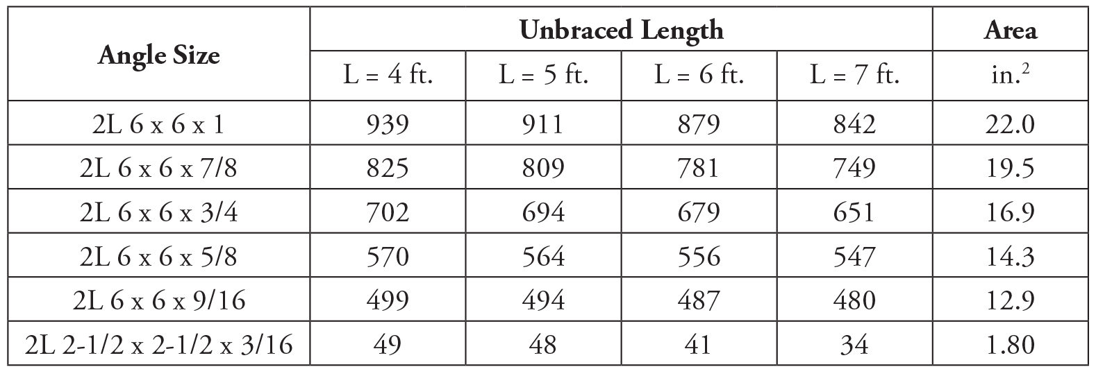
Table of available strength (LRFD) for chord angle sizes.
Cap Plate to Column Weld
The weld of the cap plate to the column must also be determined since the top plate force must be transferred into the column web. The spreadsheet uses the column T-distance as the weld length. On occasion, the base metal strength may be less than the weld strength. If this occurs, the user can select a deeper column (one with a thicker web), an additional weld can be placed beyond the T distance, or any combination of the above.
Column Web Shear
The nominal shear strength, Vn, is determined using the provisions of AISC Section G2.1 (φ = 1.0 for rolled shapes when Eq. G2-1 controls, otherwise φ = 0.90).
If the web does not have the available strength for shear, then it is generally most economical to either select a deeper W shape or one with a thicker web. The column web shear yielding is checked at the Joist Girder top chord connection independent of the column web panel zone shear.
Stiffened Seat Connection
The seat width (Ws) can be determined from the minimum bearing length and (N) from the SJI Specifications (Table 5.4-3). The reaction is located N/2 from the interior edge of the seat.
Additionally, for the stiffened seat connection, the stiffener shall be finished to bear under the seat (AISC Steel Construction Manual, Table 10-8).
Column Web Checks
The spreadsheet checks the following column web limit states:
- Web Local Yielding
- Web Crippling
- Web Compression Buckling
- Web Panel Zone Shear
The spreadsheet does not check the web panel zone shear below the bottom chord.
Web compression buckling is applicable when a pair of single-concentrated forces are applied at both flanges of a member. This condition does not exist at the exterior columns.
When unequal depth Joist Girders frame into both sides of the column web, compression buckling is checked when the stabilizer plates overlap one another. In cases when the web does not have sufficient strength for the compressive or tensile forces delivered by the stabilizer, the strength can be increased by:
- Selecting a W Shape with a thicker web.
- Adding a stiffener to the web of the column.
- Adding a doubler plate.
Bottom Chord Connection
The bottom chord of the Joist Girder must be attached to the stabilizer plate to resist and transfer the chord force to the column. Stabilizer plates are typically sized based on a ¾-inch thickness. Using a ¾-inch plate allows the plate to fit between the bottom chord angles, allowing fillet welds to be made to the heels and toes of the chord angles. Economically, the stabilizer plates can usually be connected to the column using only fillet welds. Stabilizer plates must be welded to the column flange to resist the compression and tension forces. The specifying professional must specify that the Joist Girder bottom chords be a minimum thickness to accommodate the required weld size. As is required for the top chord, the Joist Girder Manufacturer has the responsibility to check the bottom chord angles for shear lag. Case 2 from Table D3.1 is applicable for this check. For reference, the shear lag factor is calculated for the bottom chord based on the input of the angle size, bottom chord leg size, Bbc and bottom chord thickness, tbc. Providing longer length fillet welds will reduce shear lag effects.
Stabilizer Plate Checks
The following strength checks are made:
- Determine the weld between the bottom chord and the stabilizer.
- Check the Whitmore width for stabilizer (AISC Manual Section 9-3).
- Check stabilizer yielding.
- Check stabilizer Block Shear Rupture Strength.
- Determine the weld between the stabilizer and the column.
The spreadsheet uses the Joist Girder bottom chord forces to determine the weld requirements. Some designers prefer to provide enough weld to develop the full strength of the stabilizer.
Minimum Member Thicknesses
Throughout the spreadsheet, checks are made for the minimum thicknesses of base metal to match the weld strength. From the AISC Specification, Section J2.4, the design strength, φRn, and the allowable strength, Rn/Ω, of welded joints shall be the lower value of the base material strength according to the limit states of tensile rupture, shear rupture, and the weld metal strength based on the limit state of rupture.
All of the moment connection design tools can be downloaded at no cost from the SJI website: https://goo.gl/mr7MQR. The tool discussed here and the other available tools from the SJI website will assist the designer with the design of Joist Girder Moment Connections.■
A sample input sheet for the spreadsheet tool is available in the PDF to the right.