
The Northridge earthquake exposed the need for a more considered approach to seismic design. In the case of braced frames, this led to a closer examination of the behavior of the system and its components at large drifts. Engineers changed their approach to analysis, proportioning, and detailing of braced frames to avoid connection failure and other unfavorable behaviors they had observed. Simultaneously, lessons learned in the research on steel moment resisting frames, such as examination of expected material strength, were applied to the design of braced frames. The post-Northridge era also saw the introduction of the buckling-restrained brace as a useful tool in seismic design.
Background
Before the Northridge earthquake, braced frames were not the typical structural system utilized in non-industrial facilities. Past performance of braced steel frames and early research by U.S. and Japanese researchers showed the plastic energy dissipation of these systems to be poor; so moment resisting frames dominated steel construction in high seismic regions. When the 1994 Northridge earthquake exposed unanticipated damage to steel moment resisting frames (SMRF), a period of uncertainty resulted regarding the reliability and proper design methods for SMRFs. In response, the Federal Emergency Management Agency (FEMA) funded research to generate moment-frame design and construction guidelines (a joint venture known as the SAC steel project). These guidelines resulted in costly restrictions and regulations for steel moment frame construction, leading to an increase in steel braced frame popularity. Unfortunately, some of the issues that affected the performance of moment resisting frames in the Northridge Earthquake (and were addressed in the SAC steel project) could also affect the performance of braced frames.
The Problem
Due to the relative lack of popularity of braced frames, the Northridge earthquake did not expose many braced frames to intense ground shaking. Six instrumented braced steel buildings were found to have little or no damage, although ground shaking intensities at those locations were reportedly mild (Naeim, 1997, 1998). However, widely publicized reports of a single braced steel building were published and widely reviewed: a four-story office building in North Hollywood. Designed to the 1980 Los Angeles building code, and constructed in 1986, it represented a fairly modern braced frame design at the time of the event (Kelly, et. al, 2000). All damage was concentrated at the lower floor where most of the braces on a single level fractured at the mid-length or fractured at the connections. Damage to the upper story braces was minor. While this building did not collapse, the lateral resistance on the bottom floor was compromised.
In the authors’ opinion, the performance of this single building illuminated two fundamental issues with braced frames (already identified by some researchers): (i) the width-to-thickness ratio requirements (b/t) for braces were insufficient to forestall fracture when subjected to many inelastic cycles, and (ii) the design of connections proved insufficient to prevent their failure. Nearly identical behavior was reported precisely one year later during the 1995 Kobe earthquake.
Although designers tend to think of braces as governed by compression, a careful examination of research into factors affecting seismic response reveals that the stability of braced-frame structures is owed almost entirely to the behavior of braces in tension. Braces subject to compression tend to buckle at very low drifts. If these braces and their connections withstand the deformations associated with this buckling, they can maintain their integrity to resist tension forces as the direction of drift reverses. Some energy is dissipated in the first cycle of buckling; but, after that, most of the energy dissipation is a result of brace elongation. Although design requirements mandate that the number of braces in tension and compression be roughly balanced, proportioning the braced frames to have a positive post-yield behavior is not mandated by code and can be challenging. Inadequate proportioning typically results in a concentration of damage in a single story (as observed in the Northridge earthquake), further increasing brace demands. To complicate matters, the inelastic demand on braces with moderate slenderness (KL/r) results in extreme plastic hinge rotations for modest inelastic drifts.
Braces buckling out-of-plane experience severe inelastic rotation at mid-span. Rotation demands for moment connections (and corresponding section compactness requirements) provide an analogy for braces subject to flexural buckling and subsequent plastic-hinge formation, but the brace rotation demands can be much higher. Depending on brace slenderness, the plastic rotation at the mid-span hinge can exceed 10%. Pre-Northridge slenderness limits were inadequate against such extreme rotation demand and were partially responsible for the severe concentrations of damage and brace fractures with far less energy dissipation than desired.
A problem mutual to moment frames compounded this: yield strengths were much higher for materials used in braces than was anticipated (FEMA, 2000). Typical hollow structural sections (HSS) common to braced frames utilize a cold-rolling procedure which strain-hardens the steel from a nominal Fy of 46 ksi to nearly 60 ksi. This overstrength results in connections that may not be adequately designed to accommodate brace yield strengths, further limiting the expected resistance provided by the brace when frames undergo inelastic drift.
Finding a Solution
The research and design communities began to address the observations in the years following the 1994 Northridge and 1995 Kobe earthquakes. Research began to re-focus attention on assessing the adequacy of existing design provisions and typical practices with primary attention to brace selection, connection design, gusset plate detailing, and exploration of alternative design methods.
Research prior to the 1994 Northridge earthquake indicated that there is a delicate interaction between brace slenderness and rotation demands due to buckling (Goel, 1992). The more slender a brace, the lower the plastic deformation demand in the plastic hinge. This interaction was only recently quantified with modern construction detailing practices. However, multiple independent full-scale tests of wide-flange, round HSS and concrete filled tube braces demonstrated that compactness has the greatest influence on brace axial ductility. While it is important to note that concrete-filled tubes greatly enhanced brace performance for very slender sections, the behavior was nevertheless sensitive to compactness. There was no “magic bullet” to bypass this interaction, and compactness criteria were reviewed and updated to reflect this understanding.
Studies have shown that more slender braces (KL/r > 100) for shorter period buildings (i.e., less than 1.0 second) may improve post-buckling performance since slender braces sized for their compression capacity will of necessity have very high overstrength when subject to tension. When the ratio of the RyAFy to the Pcr approaches unity (that is, for stockier braces), the system is likely to have strain-hardening sufficient to distribute damage to nearby stories. The use of slender braces, however, provides an additional challenge in that connection forces are relatively large, and the braces in tension can impose large forces on columns.
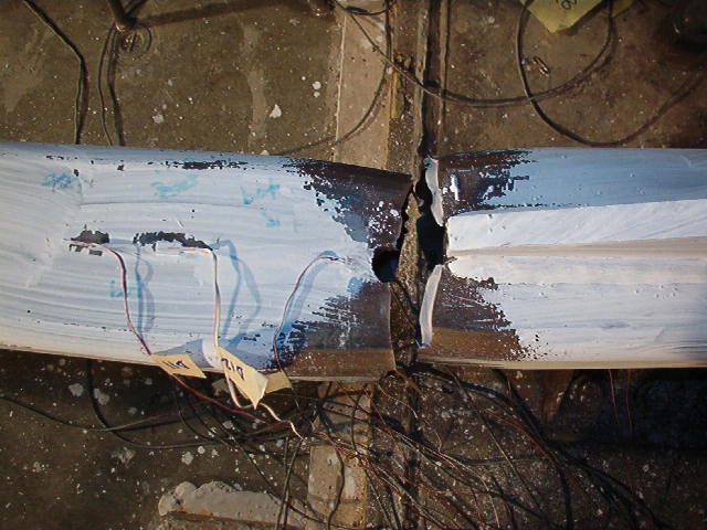
Figure 1a. Net section fracture occurring at ductilities less than expected.
Typical HSS bracing connections utilize a “knifed” gusset plate, resulting in a reduced section immediately adjacent to the gusset plate. While this “net-section” area was known to be the weak link in brace behavior, the reduction in ductility was never quantified. The research demonstrated that typical designs were not ductile, Figure 1a, whereas reinforced connections performed well. New design provisions mandated reduced sections to be designed to be stronger than the brace, allowing distributed brace yielding. Typical details now include reinforcement plates (Figure 1b).
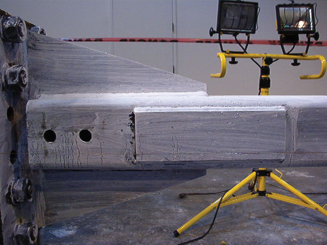
Figure 1b. Cover plate details now commonly used to increase brace ductility.
Designers have sometimes favored large gussets, Figures 2a and 2b, for questionable reasons: reduction of weld size, simplification (or misunderstanding) of “Whitmore yielding,” etc. Such large gussets may result in weld failure and gusset plate separation from the beam-column joint. New design requirements mandate this to be remedied by requiring consideration of the design of such connections for flexural forces and rotation capacity.
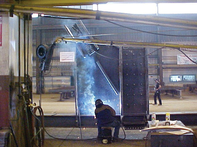
Figure 2a. Large gusset plate being fabricated.
Mitigation of local buckling and design of connections for flexural forces and rotation capacity do not adequately address the severe strength and stiffness deterioration that may occur as a result of brace buckling. This can potentially lead to significant permanent plastic deformations, extended downtime, concentration of damage in a single story, and associated collapse risk.
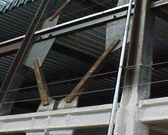
Figure 2b. Very large gusset plate installation.
Alternative bracing methods have been developed to address the issues associated with conventional buckling braces. One prominent alternative method is the buckling restrained bracing system. Although used elsewhere, these systems were unused in the U.S. at the time of the Northridge earthquake. Several large-scale tests on full assemblies demonstrated their ability to resist seismic loads in a stable, reliable manner, and nearly eliminate the severe strength and stiffness degradation associated with conventional bracing elements. Today, the buckling restrained braced frame is a common bracing system.
Changing the Code
Design practice was quick to react to the observed behavior and research immediately following the Northridge earthquake, and code requirements quickly followed. New seismic design provisions were released as early as 1997, and continuously updated as new and emerging research on braced frames was published.
Prior to the Northridge earthquake, seismic design recommendations only contained one category: “concentrically braced frames,” or CBF. Work on improving the behavior of braced frames had been ongoing for several years, resulting in the creation of the “eccentrically braced-frame” system. The 1994 Uniform Building Code (UBC) distinguished between Ordinary Concentrically Braced Frames (OCBF) and Special Concentrically Braced Frames (SCBF), with the later designed for lower forces but subject to much more stringent detailing and proportioning requirements. While OCBF are designed with little expectation of inelastic drift capacity, SCBF are designed to develop an identified plastic mechanism and withstand large seismic drifts. This SCBF mechanism includes brace buckling and tension yielding, and the associated axial (and in some cases flexural) forces required in the beams and columns.
The UBC provisions also introduced the concept of post-buckling frame behavior as a design case. Beams in chevron-braced (V-braced or inverted-V-braced) frames were required to be designed for a special load combination that applies forces corresponding to the full tension capacity of one brace in combination with 30% of the compression strength of the opposite brace, creating a significant flexural demand on the beam. Beams were required to be designed to have sufficient strength to resist this flexural demand, although the flexibility introduced was not explicitly considered.
AISC 341, Seismic Provisions for Structural Steel Buildings, has become the building-code standard for seismic design of steel systems. AISC 341 has moved (for braced frames) to defining a first-mode plastic mechanism analysis that is to be used to obtain beam, column, and connection design forces. For SCBFs, two analyses are considered: the condition on the cusp of buckling (considering full tension and compression strength), and the condition after buckling (considering the full tension strength in combination with 30% of the compression strength). The first case maximizes connection demands and overturning, while the second case captures flexural demands and forces that only appear as the system changes to a mode of behavior in which braces act predominantly in tension. This represents a continuation of the movement toward a full plastic-mechanism approach to the design of braced frames.
The Future
Continuing research has shown ways in which braced-frame behavior may be further improved. Sizemore, Fahnestock, Hines, and Bradley have studied the collapse probability of OCBF and R3BF (R=3 braced frames with no seismic detailing or proportioning requirements, allowed only in areas of relatively low seismicity). Their research included the beneficial effect of a modestly sized moment frame in forestalling or preventing story mechanisms by preventing the severe strength and stiffness degradation.
In a similar vein, Simpson and Mahin (2018), Figure 3, have developed a design method to employ a “strongback” truss to prevent the formation of story mechanisms in braced-frame structures. Integration of such an approach into the code regimen of design is problematic, but the benefits in performance are considerable.
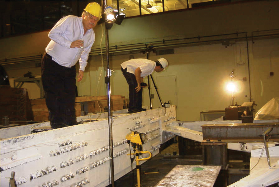
Figure 3. The authors acknowledge their debt to the late Professor Stephen Mahin, (pictured left) whose insights into the seismic response of steel braced frames (among countless other topics) has guided their work for many years.
Work by Roeder, Lumpkin, and Lehman (2011) has helped identify pitfalls in the binary approach that is common in seismic design of braced frames. By designating braces as the fuse and other elements as force controlled, the ductility demands on the brace can be quite high. In their “balanced approach” to design and proportioning, Roeder et al. (2011) have demonstrated that brace ductility demands can be reduced by allowing minor inelasticity in the connections and the beam (in chevron-braced frames). This lower ductility demand translates into greater drift capacity before brace fracture.
Performance-based design (PBD) allows for the use of a combination of elements to provide adequate reliability against collapse. For braced frames, the difference between the elastic modes of response and post-buckling modes of response can be quite pronounced. Additionally, nonlinear seismic analysis may also indicate multiple different post-buckling modes; with stiffness degradation, these may be mutually exclusive. Mean values of response quantities corresponding to radically different modes may not be as informative as considering the responses individually. Use of performance-based design to justify non-ductile detailing has been proposed but, in the authors’ opinion, the demonstration of the suitability of such designs serves more as an indication of the limitations of PBD and statistical methods than a demonstration of the reliability of a given design.
Use of performance-based design to better understand the possible behaviors of braced frames offers a more promising approach, especially when combined with design interventions (such as the strongback) that would mitigate or preclude unfavorable behaviors.■
References
Bertero, V. V., Uang, C.-M., Llopiz, C., and Igarashi, K. (1989). “Earthquake Simulator Testing of Concentric Braced Dual System.” ASCE Journal of Structural Engineering, 115(8), 1877–1894.
FEMA. (2000a). FEMA 351: Recommended Seismic Evaluation and Upgrade Criteria for Existing Welded Steel Moment Frame Buildings. Federal Emergency Management Agency, Washington, DC
Fukuta, T., Nishiyama, I., Yamanouchi, H., and Kato, B. (1989). “Seismic Performance of Steel Frames with Inverted V Braces.” ASCE Journal of Structural Engineering, 115(8), 2016–2028.
Hanson, R. D., and Martin, H. W. (1987). “Performance of Steel Structures in the September 19 and 20, 1985 Mexico Earthquakes.” Earthquake Spectra, 3(2), 329–346.
Goel, S. C. (1992), “Earthquake Resistant Design of Ductile Braced Steel Structures,” Stability and Ductility of Steel Structures under Cyclic Loading, pp. 297-308, CRC Press, Boca Raton, FL
Kelly, D. J., Bonneville, D. R., Bartoletti, S.J., (2000) 1994 Northridge Earthquake Damage to a four-story Steel Braced Frame Building and Its Subsequent Upgrade, Proceedings, 12th World Conference on Earthquake Engineering, Auckland, New Zealand New Zealand Society for Earthquake Engineering.
Naeim, F. (1997). Performance of Extensively Instrumented Buildings During the January 19, 1994 Northridge Earthquake, John A Martin and Associates, Research and Development Department, Los Angeles, CA 90015.
Naeim, F. (1998). “Performance of 20 Extensively Instrumented Buildings During the 1994 Northridge Earthquake.” The Structural Design of Tall Buildings, 7(3), 179–215.
Roeder, C, Lumpkin, E, and Lehman, D (2011); “A balanced design procedure for special concentrically braced frame connections” Journal of Constructional Steel Research, 67(11), pp 1760-1772, http://dx.doi.org/10.1016/j.jcsr.2011.04.016
Sizemore, J.G., Fahnestock, L.A., Hines, E.M. and Bradley, C.R. (2017) “Parametric Study of Low-Ductility Concentrically-Braced Frames under Cyclic Static Loading,” Journal of Structural Engineering, 143(6). http://dx.doi.org/10.1061/(ASCE)ST.1943-541X.0001761
Simpson, B and Mahin, S (2018); “Experimental and Numerical Investigation of Strongback Braced Frame System to Mitigate Weak Story Behavior,” Journal of Structural Engineering, 144(2) doi:10.1061/(ASCE)ST.1943-541X.0001960