
Stacking Innovation by the Caspian Sea
The population of Baku, the capital of Azerbaijan, has rapidly increased in the past decade. The resulting growth in urban activity has transformed the city into the Caspian Sea region’s hub, with new high-rise buildings and lively cultural centers creating a unique, well-balanced, and organically blended futuristic composition. The recently-topped-out 555-foot-tall Ministry of Taxation (MOT) tower has revitalized the skyline of Baku. It features five twisted stacked cubes that are independently cantilevered from a circular central core. Each cube holds five office floors and a column-free green roof terrace providing a distinct separation from the next cube above. Each floor plan is rotated 1.2 degrees with respect to the floor below, resulting in an astonishing 40 degrees twist overall from bottom to top (Figure 1).
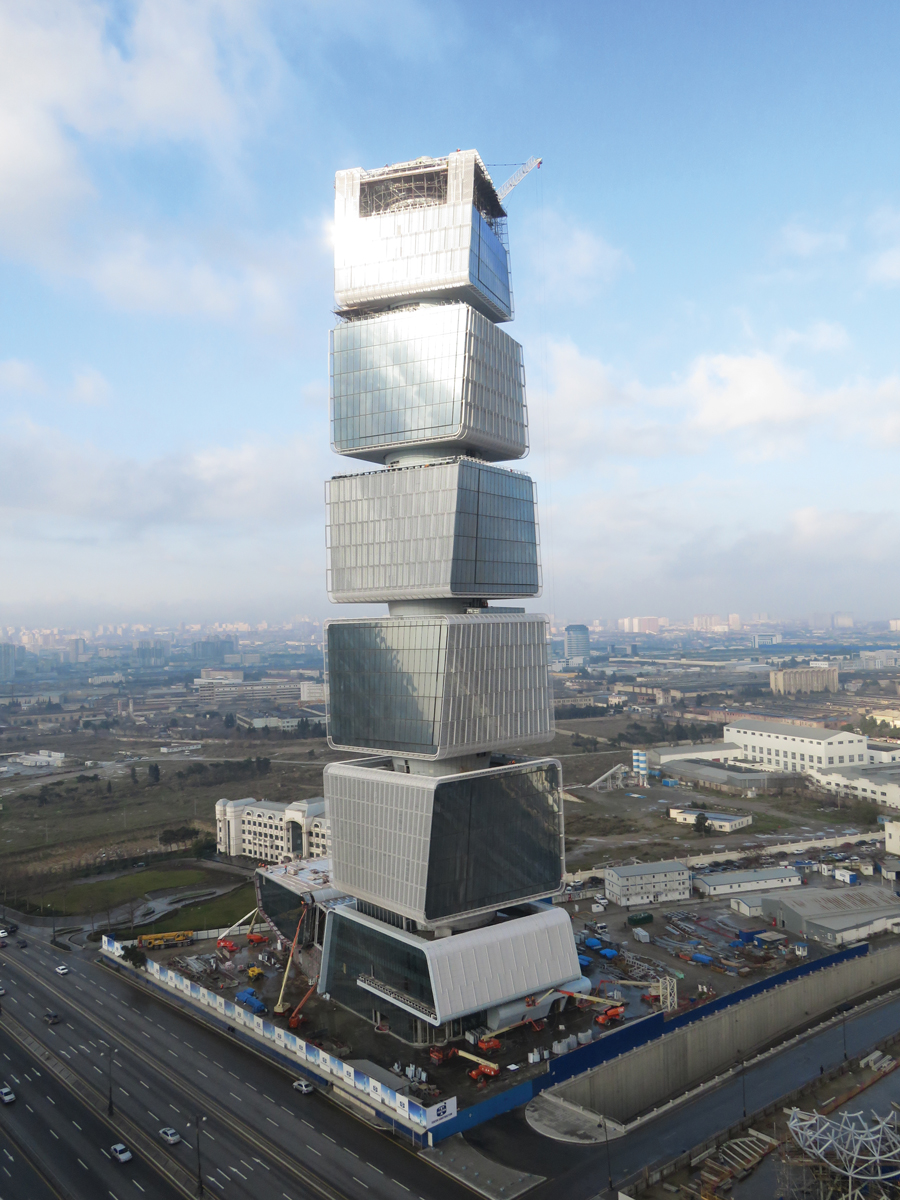
Figure 1. Topped-out tower. Courtesy of Tekfen Construction.
Inherent Structural Challenges
At 32 stories, MOT tower is not exceptional in height but it posed particular challenges due to unique features central to its iconic design. First, the separate stacked cubes, and column-free terraces between them, required picking up eight perimeter columns on 50-foot-long cantilevers from the central core, with 33-foot cantilevers from the columns to the extreme corners of each floor. In addition to the undulating form of the building, its geolocation within the highly-seismic Caspian Sea region pushed the building into Seismic Design Category D, with Site Class D soil, thus increasing the code-required demand on the structural system. Performance-Based Design was utilized to verify the adequacy of the seismic design and special seismic detailing was provided where required per code. High wind demand was an added challenge; basic wind speed for the region is 118 mph. Internationally accepted codes and specifications for building construction from authorities such as ASCE, ACI, and AISC were used for tower design references. ETABS and Perform-3D, both CSI analysis software products, were primary tools used for the design of the superstructure.
Transfer System Analysis and Detailing
The column-free terraces between adjacent cubes required transferring all column loads at the base of each cube through trusses cantilevered from the core. An innovative design solution for the eight trusses per cube has vertical load from the columns above carried through steel diagonal web members, while the induced moment from a 50-foot-long cantilevered truss is resisted by a force couple from tension and compression in the slabs integral with truss top and bottom chords. This reflects realistic compatible behavior at chords and slabs (Figure 2).
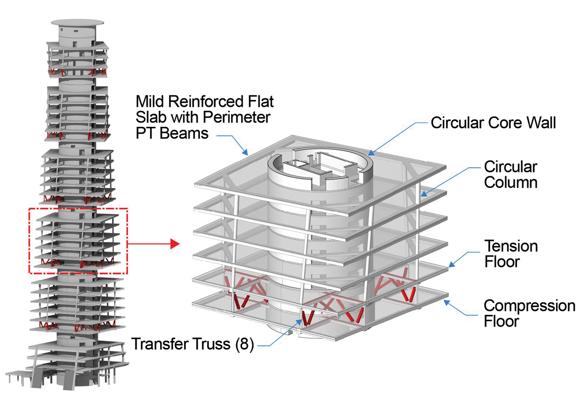
Figure 2. Primary structural components.
Cantilever truss chord forces of similar magnitude occur on opposite sides of the tower. Designing the transfer floor slabs as “tension rings” and “compression rings” that balance gravity cantilever chord forces was beneficial, simplifying both load path and connections. Because horizontal forces are designed to bypass the core, truss connections to the core only needed to resist vertical loads and the core wall was not tasked with resolving the large coupling forces generated by the 50-foot cantilevers. Reinforcement of slabs in tension was optimized using nonlinear finite element models with layered shell elements to simulate accurate cracking behavior of the concrete slab under tension loads. In addition, overall stability was analyzed for a variety of unbalanced live load patterns to ensure each cube remained stable and secure under eccentric loading conditions. In these situations, the core resists modest unbalanced forces applied through slab bearing.
Cantilever truss tip deflections received close attention throughout the design process, as excessive deflection would not only become unsightly but could also cause unwanted strain on the façade panels. Since slab tension and compression was relied on for truss chord forces, long-term deflection predictions reflected concrete creep and shrinkage effects over the life of the building. Trusses were detailed, fabricated, and constructed with upward camber to compensate the anticipated large instantaneous deflection at their outer ends (Figure 3). Relative long-term deflections along the perimeter of the floor plate were coordinated with the façade consultant to ensure the façade joint and connections were detailed accordingly.
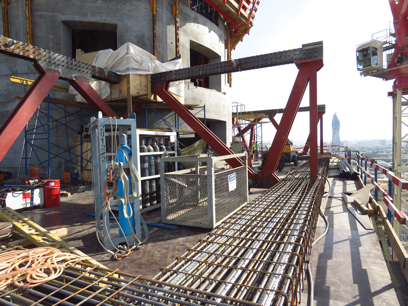
Figure 3. Transfer truss construction. Courtesy of Tekfen Construction.
Construction Sequence Challenges
Relying on tension and compression slabs to resist cantilever truss chord forces meant the transfer system was not complete until both tension and compression slabs were cast, cured, and achieved design strength. For this reason, the transfer trusses (and the wet weight of the slabs) required shoring, an added challenge for the design and construction team.
However, by choosing steel trusses for the main vertical load-transferring element, the amount of shoring required during construction was dramatically reduced. Other options, such as concrete shear or corbel walls, would have required shoring of more than one cube to engage multiple transfer walls to support the added weight of the concrete walls; relieving this requirement allowed for rapid progression of construction for lower cubes and a reduction in the overall construction schedule.
Construction staging and sequence analysis were performed to ensure the construction weight of each cube’s transfer system (steel truss and weight of concrete) could be supported by the transfer system of the cube below. This sequencing analysis served as the controlling load case for transfer truss design strength (Figure 4).
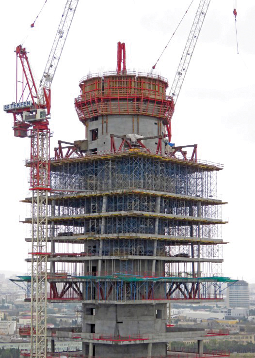
Figure 4. Shoring the transfer system. Courtesy
of Tekfen Construction.
Lateral Load Resisting System
A centrally located circular reinforced concrete core wall runs the entire height of the building to resist lateral loads and to support gravity loads. The wall transitions in thickness at three points along its height, varying from 6 feet thick at the base to 2 feet at the top, while the core inside radius remains 26 feet throughout.
The walls experience highly concentrated compression stresses at transfer truss diagonal bearing points, where columns transfer their gravity loads back into the core wall. Additional compression stresses will occur during seismic events when the core walls are resisting high overturning moments. As a result, determining locations that would require proper concrete confinement detailing was essential.
Core wall acceptance followed a Performance-Based Design approach. Nonlinear Response History Analysis, using realistic earthquake records and post-yield structural element properties, was used to analyze and guide detailing of the core wall. Where combined seismic and gravity loading was found to result in high compressive demands, confinement reinforcement meeting ACI 318 requirements was provided to enhance concrete performance under cyclic loadings. These conditions occurred throughout the tower height. High confinement was also provided around the transfer trusses due to the sudden increase of compressive forces in the core wall, as well as to aid in preventing pull-out of the trusses.
Coupling beams were the major fuse elements to absorb seismic energy and to limit seismic forces applied to other elements. The nonlinear response history analysis results were beneficial in optimizing their design. Nonlinear results revealed that most of the coupling beams could be designed with conventional reinforcement while still following capacity design principles; shear reinforcement is sufficient to have flexural hinging occur at beam ends without shear failure. At floors with significant plastic rotation demands, diagonal reinforcement was provided to ensure ductile behavior under cyclic seismic loads.
Azerbaijan’s New Twist
Innovative structural solutions were developed to support five twisting cubes, each consisting of five office levels and a column-free roof terrace. Advanced structural analyses, including seismic performance nonlinear analysis and construction staging and sequence analysis, were used to design and confirm that tower strength, safety, and serviceability requirements would be achieved. These efforts were essential to developing a practical, constructible design that made this tower possible. Upon reaching structural top-out in April 2018, the unique and futuristic shape of MOT tower became a new national landmark of Azerbaijan.
We want to acknowledge the Tekfen Construction team – Bulent Guney, Muharrem Arslan, Baris Altiparmak, Ahmet Cobanoglu, Ertac Yildiz, Alper Celen and Arcan Aksakaloglu – for their support and contributions to this unique project, as well as the Design Architect, FXCollaborative.■