
Not Your Typical Office Building!
Most office buildings are boring, very boring. They are typically rectangular or square in plan, standard 25-foot x 25-foot repeating bays of framing with repetitive floor-to-floor heights, and are not something engineers and architects get too excited about. The Krause Gateway Center in Des Moines, Iowa, does not challenge this notion; it redefines it, completely. The typical constructs of an office building are still present (open floor plan, large conference rooms, on-site parking) but the atypical aspects of the project separate it from the pack.
The 6-story, 100-foot-tall, 160,000-square-foot building is framed using structural steel beams and columns. The double height lobby (29 feet tall), 60-foot and 30-foot column spacing, extreme cantilevers beyond the façade, the transparency of the lower floors (the entire building is wrapped in glass to enhance the view to the sculpture park across the street), and the need for a thin structural sandwich to accommodate the desired floor to floor heights and MEP runs create structural challenges rarely seen in a building of this use and type.
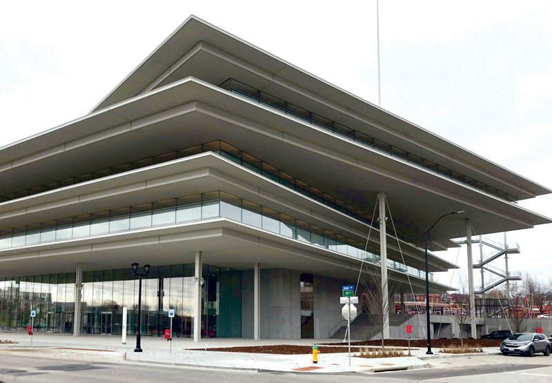
Finished Center (looking at the southeast corner of the building).
The design of the building followed the 2012 International Building Code (IBC) as stipulated by Article III of the Des Moines, Iowa, Code of Ordinances. Other standard additional design codes such as ASCE 7-10 (Minimum Design Loads for Buildings and Other Structures), ACI 318 (Building Code Requirements for Structural Concrete and Commentary), and the American Institute of Steel Construction (AISC) Design Guides were utilized for loading requirements and material specific requirements.
The building structure at and below grade is all cast-in-place concrete supported by over 450 one-hundred-ton axial capacity auger cast concrete piles.
There are a multitude of factors that contributed to the challenges faced when framing the Krause Gateway Center for support of the main gravity and live loads. The second floor of the building was set back from the building façade (which is inset from the building perimeter above) on 3 sides, creating a double height lobby between the ground and 3rd floors. The 3rd and 4th floor were each larger in plan than the one below it. The 5th floor was larger than the 4th and rotated clockwise, about 16 degrees from the buildings face on the west side. The 6th floor followed the geometry of the 5th floor below and included a small “pop-up” for the elevator over-run and public access to the roof above it. Structural steel was chosen for the need to be flexible (both literally and figuratively) and its multi-faceted ability to solve many different problems with one trade to solve these geometric challenges.
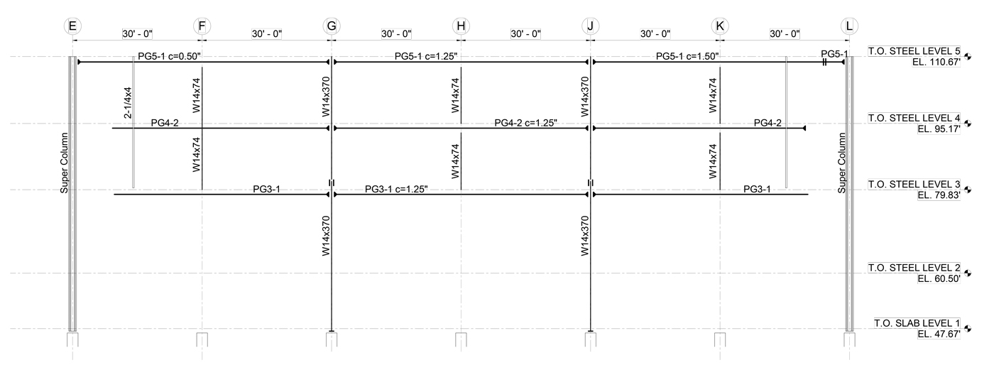
Figure 1. Frame elevation at grid 7.
The typical slabs are framed with 3 inches of normal weight concrete on a 2-inch 18-gage metal deck spanning 10 feet between floor beams. The standard floor beams (however few of them there were) are 30 feet long W10x49s with sixty-five ¾-inch-diameter headed shear studs with a 1-inch camber to meet deflection criteria and allow space for MEP runs below them. The girders, also spanning 30 feet, were typically W27x84s with web penetrations to accommodate the MEP runs. At the perimeter of the 3rd floor, a 60-foot column spacing is maintained to allow for a column-free space around the main entrance lobby. This leads to the need to transfer out the columns that are spaced at 30 feet on-center at the 4th and 5th floors. However, the floor plate of the 3rd and 4th floor is smaller than that of the 5th floor, so the beams that transfer out the columns at the 3rd and 4th floor all must be hung from the 5th floor, which is supported by 62-foot-4-inch-tall unbraced super columns (see the frame elevation in Figure 1). Each of the transfer beams at the 3rd and 4th floor, as well as the ones at the 5th floor supporting all of the building loads from floors 3 and 4, have a strict 27-inch depth restriction. With ultimate moments ranging from 3,000 kip-feet (at the 3rd and 4th floor) to almost 5,000 kip-feet at the 5th floor, standard rolled shapes did not fit the bill and built-up plate girders were utilized. A typical plate girder at the 3rd floor uses grade 50, 2½-inch-thick 23-inch-wide flanges with a 21-inch-deep by 1-inch-thick web. As noted above, the 3rd and 4th floor were hung from the 5th floor using two 2-inch-diameter 75 ksi solid rods.
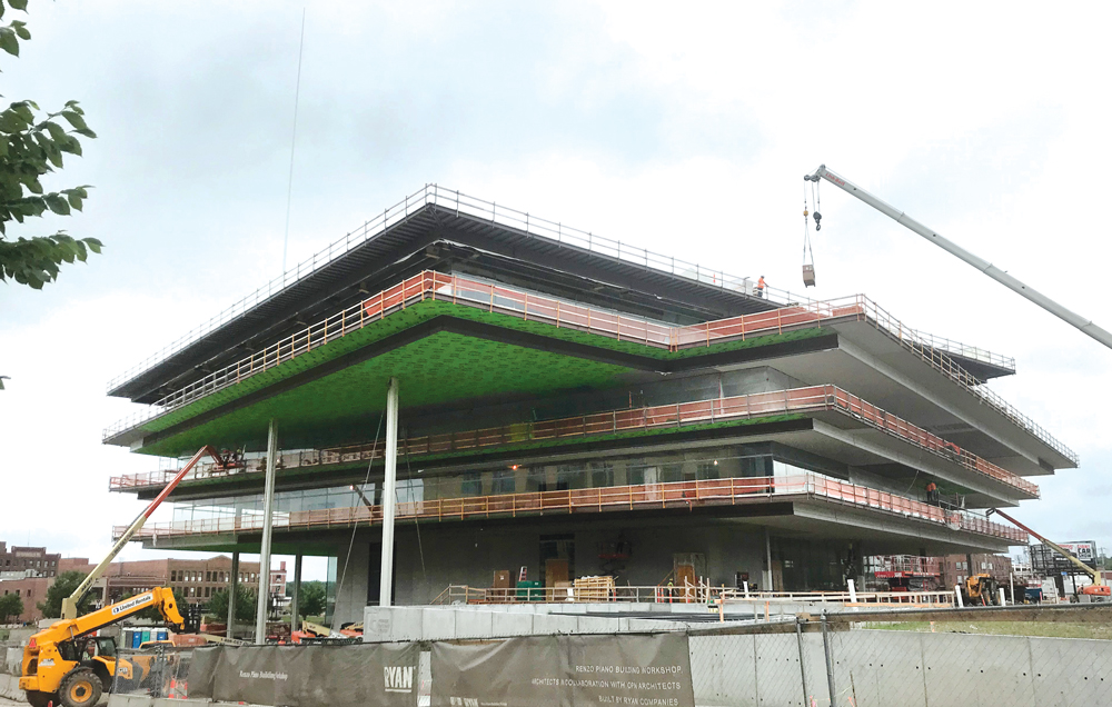
Figure 2. The northeast exterior face of the building during construction (note super columns are supporting 5th and 6th floor).
The lateral framing for the building is a hybrid of moment frames, braced frames, and cable-tied super columns. A response modification factor of 3 (not specifically detailed for seismic resistance) was utilized for seismic design with 115 mph 3-second gust for Main Wind Force Resisting System (MWFRS) loads. Two cross braced frames are provided at the elevator core of the building, as the transparent glass façade throughout the building does not allow for cross bracing at the perimeter. Moment frames are provided throughout the building to supplement the braced frames. The double height space between the 1st and 3rd floors create 32-foot-tall moment frames, complicating an already inherently flexible lateral load resisting system. The moment frame/braced frame system was not enough to meet code-stipulated seismic drift criteria and project-desired wind drift criteria (building height/360). The design team found a way to strike a balance between the two by using cable ties at the exterior 62-foot-4-inch-tall super columns to help control drift. The four super columns are unbraced columns that span from the ground floor to the 5th (west side of the building) and up to the 6th floor (east side of the building) outside of the perimeter of the 2nd, 3rd and 4th-floor plates (Figure 2). The super columns are custom built up shapes using 50 ksi plates. The additional challenge discovered when using the super columns and attaching tension rods (at an angle from the top to the base) was limiting the amount of load the rods take so that the structure that the rods attached to at the base did not need to be too large. To continue to control drift and limit the amount of load the tension rods could take, the design team worked with TriPyramid and developed connections (from the tension rods to the base structure) using a fuse pin and an internal spring cartridge to limit the loads in the tension rods to 35 kips. The structural team used the non-linear mode in an ETABS analysis model to quantify the noted 35-kip load, and the cable-tied super column’s contribution to the overall systems drift resistance.
The showpiece of the Krause Gateway Center is the perimeter exterior cantilevered framing, affectionately known as the “nosing” by the design and construction team. The nose is a two-level exterior cantilever built using two channels, 3⁄8-inch-thick plate, C5x9 vertical channels, and two HSS tubes spanning between wide flange beam outriggers. The wide flange beam outriggers cantilever 9 feet 2 inches up to 19 feet out from their main support points (columns or perpendicular beams) and support the 7-foot-long cantilevered nosing. The extreme cantilevers produced significant deflections and torsion at the outrigger endpoint which were mitigated by kinking the outriggers up at their support point anywhere from ¾ inch to 5 inches. A critical factor was the need to attach (in plan) each of 60-foot-long sections of the nose to each other so that the entire system acted together, and the outriggers did not differentially deflect. To accomplish this, the design team worked closely with the construction team to develop a pre-loading program which pre-deflected the outriggers to their expected fully loaded levels before the nosing was attached and leveled.
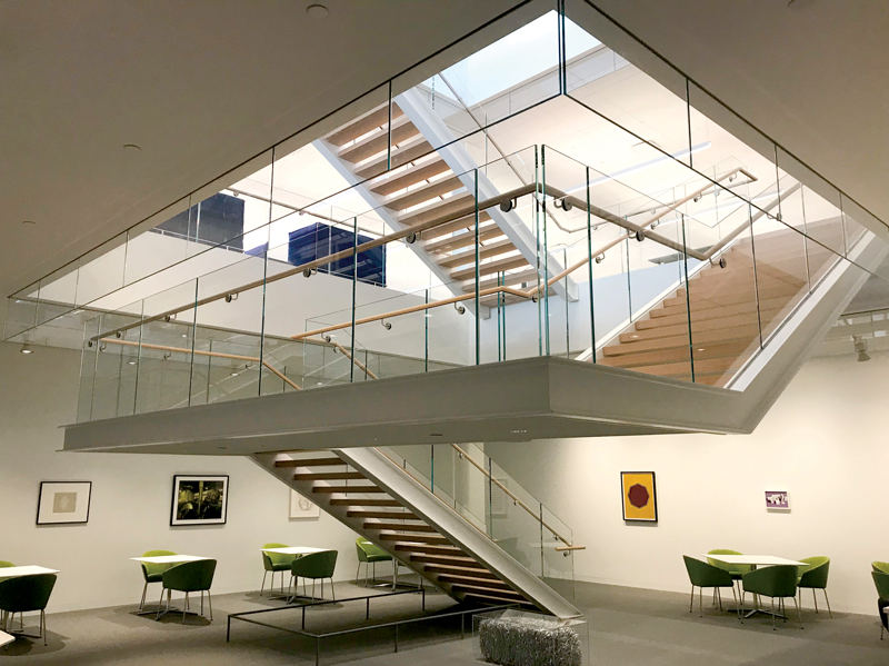
Figure 3. Free-floating interior stair between 3rd and 4th floor.
The Krause Gateway Center is the headquarters for the Kum & Go Corporation and other local businesses. The finished product provided open site lines, column-free workspaces, and an abundance of natural light that offers stunning views to the surrounding streetscape and park. There are additional structural challenges, too numerous to describe here (the free-floating stairs [Figure 3], façade support, and 1,400 beam penetrations, to name a few), along with the design ambitions described above that enabled the architect’s and owner’s visions to be achieved using structural steel in new ways not typically seen in a standard office building.■
Project Team
Owner: Kum and Go
Architect: Renzo Piano Building Workshop with OPN Architects
Structural Engineer: Silman
Façade Engineer: Front
Construction Manager: Ryan Companies
Steel Contractor: LeJeune Steel Company
Steel Erector: Danny’s