
This article presents an alternative method for designing concrete flat slabs subjected to flexure-induced punching. The design method meets the requirements of ACI 318-14, Building Code Requirements for Structural Concrete and Commentary, Canadian Standard CSA A23.3-14, Design of Concrete Structures, and recommendations of ACI 421.1R-08, Guide to Shear Reinforcement for Slabs, and ACI 421.2R-10, Guide to Seismic Design of Punching Shear Reinforcement in Flat Plates. The flexural reinforcement above the columns in two orthogonal directions should not be less than a calculated minimum amount to resist flexure-induced punching. Insufficient flexural reinforcement would induce wide flexure cracks extending deep in the slab thickness and, if these cracks joined a shear crack, a punching failure would result.
Shear Reinforcement
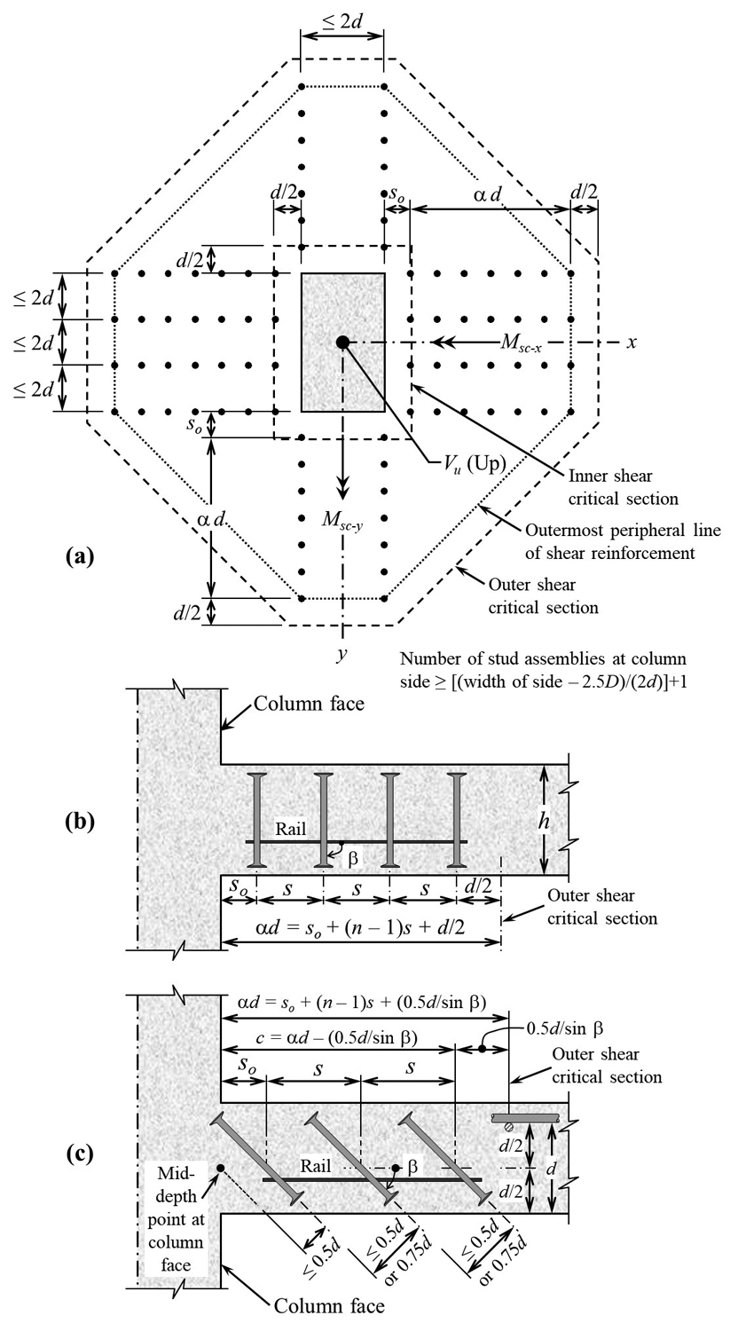
Figure 1. Stirrups or headed stud shear reinforcement; a) Sectional plan at the middle of d, (b or c), Sectional elevation, vertical or inclined studs (assembled by a rail).
Figure 1a shows a sectional plan at d/2 from the compression face of a solid slab reinforced against punching with headed studs or stirrups, with d equal to the average distance from extreme compression fiber to the centroid of tension reinforcement in two directions. The shear force, Vu, and moments, Msc-x and Msc-y, which are transferred from column to slab, are shown in their positive directions in Figure 2; x and y are orthogonal principal axes passing through the centroid of an assumed shear critical section perimeter. Figure 1b shows a typical assembly of vertical headed studs; inclined headed studs are depicted in Figure 1c. The governing Equation 1 applies at inner and outer shear critical sections (Figure 1a).
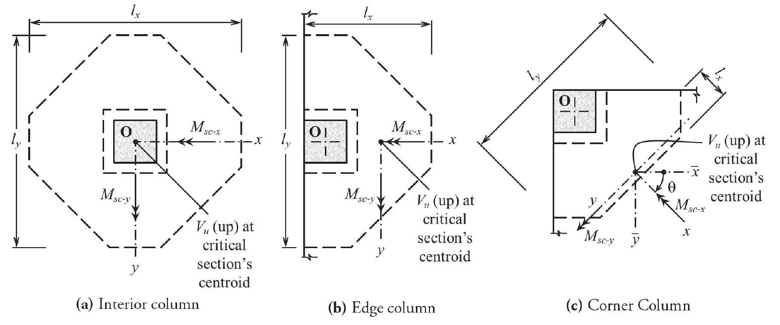
Figure 2. Positive sign convention of factored internal forces transferred from columns to slabs. The centroid and principal axes are shown for the outer critical section only.
vu ≤ ϕ vn (Eqn. 1)
where vu is the largest absolute value of factored two-way shear stress calculated at the perimeter of the critical section; ϕvn is the nominal two-way shear strength, multiplied by strength reduction factor ϕ; in ACI 318-14, ϕ = 0.75 (equivalent ϕ = 0.65 in CSA A23.3-14). At the inner critical section, the nominal strength is:
vn = vc + vs (Eqn. 2)
where vc and vs are the nominal shear strength provided by concrete and shear reinforcement, respectively.
The requirements for flexural reinforcement in codes (which is not reviewed here) may also satisfy Equation 3. To resist flexure-induced punching, the top two-way flexural reinforcement above the column should satisfy Equation 3 (in addition to the code):
Vu ≤ ϕflex Vflex (Eqn. 3)
where Vu is the upward factored shear force transferred from column to slab, with eccentricities (Msc-x/Vu) and (Msc-y/Vu), ϕflex = 0.9 or 0.85 (flexural strength reduction factor in ACI 318-14 or CSA A23.3-14, respectively), and Vflex is the shear force that develops a local flexural yield-line mechanism. The value of Vflex is determined by yield-line analysis. Equation 3 is used to determine a minimum flexural reinforcement at the top of the slab in a zone above the column. The provisions of ACI 318-14 are sufficient for the design of flexural reinforcement for factored loads, and they are often sufficient to satisfy Equation 3. When Equation 3 shows a requirement for additional flexural reinforcement above the column, bottom reinforcement near mid-span can be reduced (while satisfying static equilibrium).
The provisions of ACI 318-14 and CSA A23.3-14 are intended for the crucifix layout of shear reinforcement (Figure 1a). The two codes do not explicitly require satisfying Equation 3 for safety against flexure-induced punching. In the crucifix layout, the stud assemblies are placed perpendicular to column faces and, close to each of its corners with spacing between assemblies measured parallel to the column, faces are less than or equal to 2d.
The number of assemblies at a column face is greater than or equal to 1+ [(column width – 2.5D)/(2d)]; where D = stud diameter. A column with a circular cross-section or other shape may be treated as a square or rectangular column of equal area.
Flexure-Induced Punching
A general criterion (Equation 3) supplements ACI 318-14. Yielding of the top flexural reinforcement in a zone above a column can induce punching failure. This flexure-induced punching can occur when a pattern of yield-lines develops a local mechanism. A simplified equation for Vflex is derived below.
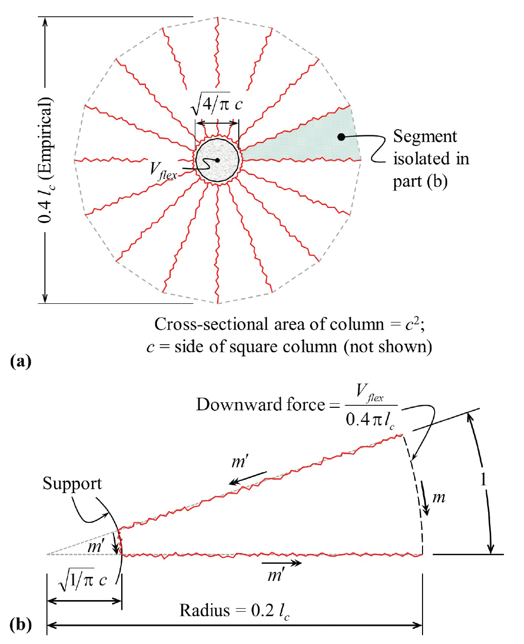
Figure 3. Assumed yield-line pattern for the derivation of Eqn. 5; a) Overall mechanism, b) Forces and moments on one of the segments forming the mechanism.
Equation 4 gives Vflex, corresponding to yield-line mechanism in Figure 3a, in which an isotropic slab is supported on circular columns of area equal to c2. The same yield-line pattern is assumed with square columns of sides equal to c; the same pattern is also assumed for other columns with cross-sectional area equal to c2. Equilibrium of an isolated slab (Figure 3b) gives (by taking moments about the inner edge of the segment):
Equation 4
Equation 4 may be rewritten as:
Vflex = 2π (m‘ + m)/(1-2.8c/lc) (Eqn. 5)
where m‘ and m are the absolute values of ultimate flexural strength per unit width provided by the top and bottom reinforcement, respectively, and lc is the center-to-center distance between columns. In isotropic slabs, the value of m‘ or m is the same in any orientation. For a non-prestressed slab, m‘ (or m) can be expressed in terms of flexural reinforcement ratio ρ’ (or ρ):
m‘ = ρ’fyd2[1‒0.59(ρ’fy/f’c)] (Eqn. 6)
where fy is the yield strength of flexural reinforcement and f’c is the specified compressive strength of concrete.
Consider a concentric force, Vu, at the centroid of the inner shear critical section. To determine the minimum non-prestressed flexural reinforcement to avoid flexure-induced punching for a given value of Vu, substitute Vflex by the given value in Equation 5 to obtain m’; then, solve Equation 6 for ρ’. To avoid flexure-induced punching (Equation 3), provide a minimum top flexural reinforcement ratio above the column, considering the reduction factor ϕflex (= 0.9 or 0.85).
ρ’min = ρ’/ϕflex (Eqn. 7)
Flexure-induced punching may occur at a load smaller than Vflex, without the full development of a yield-line mechanism. In such a case, Equation 4 gives a value of flexural strength greater than required; a slightly smaller value may be sufficient. For a prestressed slab with known prestressing, the required reinforcement is determined for m’ minus the flexural strength provided by the prestressed tendons. The minimum top flexural reinforcement should extend in orthogonal directions to cover the yield-line pattern in Figure 3, plus development lengths. When the spans in x and y directions are different, the reinforcement may be orthotropic. For an orthotropic slab with positive and negative moment resistances m and m’ in the x-direction and αm and αm’ in the y-direction, substitute the orthotropic slab within the yield line pattern by an affine isotropic slab with moment resistances m and m’, but with linear dimensions in the x-direction multiplied by (α)‒1/2 and Vu transformed to Vu (α)‒1/2. For simplicity, it would be safe to calculate ρ’min for an isotropic slab having the larger span in both directions.
When Vu is eccentric with respect to the centroid of the inner shear critical section, apply Equation 5, setting Vflex = vubod; where vu = largest shear stress – in absolute value – at the inner critical section (Equation 11, derived in the examples provided in the online version of this article). The use of Equation 5 when Vu is eccentric errs on the safe side.
Example 1: Minimum Reinforcement for Flexure-Induced Punching
Determine the minimum top flexural reinforcement ratio ρ’min of a solid flat plate. Assume: square columns of side c = 0.06 lc; where lc is the center-to-center distance of columns in two orthogonal directions, factored load, qu = (106.1h + 638.1)×10-3 pound/inch2, with h as the slab thickness in inches, Vu = qul2c (at the centroid of the inner shear critical section) and m = m’/4. Vary h and lc as in Table 1. Take f’c = 4350 pound/inch2; fy = 58×103 pound/inch2; ϕflex = 0.9. Equations 5-7 give the values of m’, ρ’, and ρ’min in Table 1. Assume that Vu is at the centroid of the inner shear critical section.
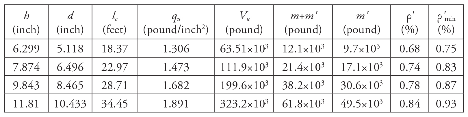
Table 1. Design Example 1: Calculation of m‘, ρ’ and ρ’min (Eqns. 5-7).
Summary and Conclusions
Resisting flexure-induced punching requires a minimum amount of top flexural reinforcement above the column. The minimum reinforcement is determined by yield-line analysis of a local mechanism; the minimum value depends mainly upon Vu and d. Equations are reviewed for the design of headed studs or stirrups as shear reinforcement arranged in a crucifix layout. The shear reinforcement is placed on equally spaced peripheral lines. The number of lines is determined by repetitive calculation of the maximum shear stress at the outer critical section to satisfy the governing equation: vu ≤ ϕvn (= ϕvc; reference is given, with examples). The properties of the shear critical section perimeter are calculated with reference to principal axes.
The shearing force transferred between slab and column is generally combined with a moment. Fractions γvx and γvy of the transferred moment components in x and y directions contribute to the value of vu. The coefficients γvx and γvy are calculated by equations depending upon the shape of the critical section. The design involves repetitive computations, conveniently done with a computer. Ignoring principal axes, leaving out one of the two components of the transferred moment, or arbitrary reduction of γv gives erroneous results. Stud assemblies are placed perpendicular to column faces and close to each of its corners. The spacing between assemblies is less than or equal to 2d (Figure 1a).■
References
American Concrete Institute Committee 318, 2014, Building Code Requirements for Structural Concrete, ACI 318-14 and Commentary, American Concrete Institute, Farmington Hills, MI 48331, USA.
Canadian Standard Association, 2014, Design of Concrete Structures, CSA A23.3-14, 5060 Spectrum Way, Suite 100, Mississauga, Ontario, Canada L4W 5N6.
Gayed, R.B., Peiris, C. and Ghali, A., 2017, “Flexure-Induced Punching of Concrete Flat Plates,” American Concrete Institute, fib Bulletin 81, March, pp. 73-100.
Ghali, A., STDESIGN: Computer program for design of headed stud shear reinforcement, DECON, www.constud.ca, 2018.
Ghali, A. and Neville, A.M., 2017, Structural Analysis: A Unified Classical and Matrix Approach, CRC Press, Taylor and Francis Group, 7th ed., 933 pp.
Ghali, A. and Gayed, R.B., 2019, “Universal Design for Punching Resistance of Concrete Slabs,” ACI Structural Journal, Vol. 116, No. 1, January.
Johansen K.W., 1962, Yield-Line Theory, Cement and Concrete Association, London, England, 181 pp.
Joint ACI-ASCE Committee 421, 2008, Guide to Shear Reinforcement for Slabs, ACI 421.1R-08, American Concrete Institute, Farmington Hills, Michigan, 23 pp.
Joint ACI-ASCE Committee 421, 2010, Guide to Seismic Design of Punching Shear Reinforcement in Flat Plates (ACI 421.2R-10), American Concrete Institute, Farmington Hill, MI, 30 pp.
Szilard, R., 1974, Theory and Analysis of Plates, Prentice Hall, 724 pp.
Eccentric Shear Stress Model and Examples 2 to 4
Calculation of vu
The factored shear stress vu is assumed constant over d and linearly varying with x and y; where (x, y) = coordinates of a point on the critical section perimeter. Thus,
vu = c1+c2 x+c3y (Eqn. 8)
The point (x, y) at which vu is maximum is determined by trial. The constants c1, c2, and c3 are determined by the equilibrium conditions:
Vu = d∫vudl ; Msc−x = d∫vuydl ; Msc−y = d∫vuxdl (Eqn. 9)
where dl = elemental length of the critical section perimeter. Substitution of vu from Equation 8 in each of the three equations listed in Equation 9 and solving for the constants gives:
Equation 10
where Ac = bo d = area of critical section; bo = length of its perimeter; Ix and Iy = moments of inertia about x– and y-axes, respectively; Ixy = its product of inertia. Because x and y are principal axes, Ixy = 0 and Equation 10 can be written as:
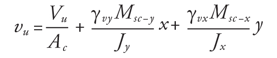
Equation 11
where Jx or Jy = d Ix or d Iy, respectively. Shear stress is induced by a fraction γvx or γvy of the moment transferred between the slab and column. Equation 11 is used to determine (by trial) the largest absolute value of vu.
Geometry Parameters Ac, Jx, Jy, and Ixy
The perimeter of the shear-critical section is partitioned into straight line segments of length ls; the total length of the perimeter = bo = Σls. The values of the geometry parameters are given by:
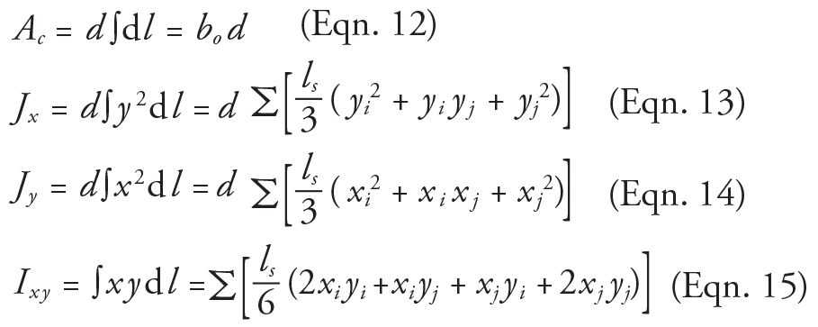
Equations 12-15
where (xi, yi) and (xj, yj) = coordinates of points i and j at the extremities of a typical segment whose length is ls.
Principal Axes
Figure 2c depicts non-principal axes x and y the moments of inertia and the product of inertia about axes x and y have been determined. The orientation of the principal axes and the values of Ix and Iy of the critical section perimeter (Figure 2) can be determined by Equations 16-18.
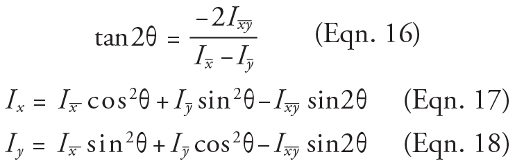
Equations 16-18
Coefficients γvx and γvy
The coefficients γvx and γvy depend upon the shape of the considered critical section. Equations 19-21 are used at the interior, edge, and corner columns (Figure 2). ACI 318-14 gives Equation 19; Equations 19 to 21, based on finite element studies, are adopted in ACI 421.1R-08. The coefficients γvx and γvy are expressed as functions of the projections lx and ly of the perimeter of the critical section on directions of principal axes x and y:
Interior column-slab connections (Figure 2a):
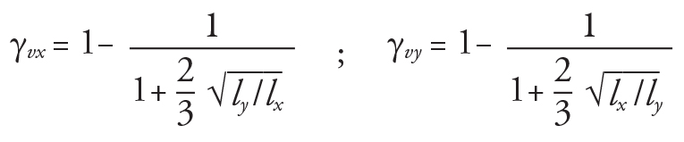
Equation 19
Edge column-slab connections (Figure 2b):
Equation 20
Corner column-slab connections (Figure 2c):
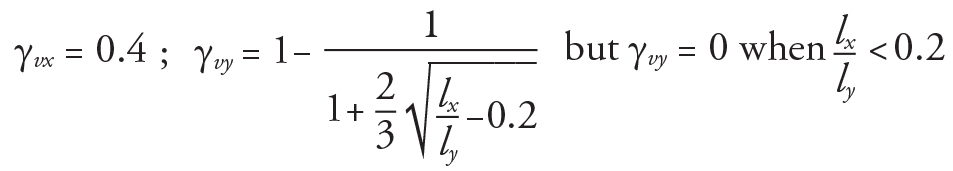
Equation 21
Nominal Shear Strength vc
Without shear reinforcement, the nominal shear strength provided by concrete at the critical section at d/2 from the face of support is given by:
vc = 4λ√f’c (pound/inch2) (Eqn. 22)
where λ = reduction factor for light-weight concretes as defined in ACI 318-14, 19.2.4.2.
In applying Equation 2 (using headed studs or stirrups), the nominal shear strength provided by concrete at the inner critical section (Figure 1a) is given by Equation 23 or 24, respectively.
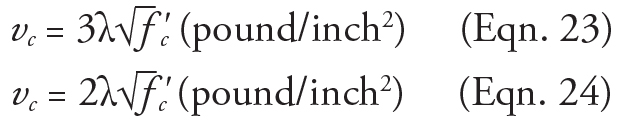
Equation 23-24
Equation 24 applies also at the outer critical section (with vs = 0).
Nominal Shear Strength vs
With inclined or vertical shear reinforcement, vs is given by:
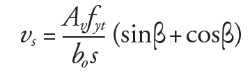
Equation 25
where β = angle defined in Figures 1b and 1c; with vertical legs of stirrups, β = 90°; Av = area of the shear reinforcement legs on one peripheral line parallel to the perimeter of the column; fyt = specified yield strength of shear reinforcement.
The distance so between the face of support and the innermost peripheral line of shear reinforcement is limited by Equation 26; the spacing s between consecutive peripheral lines is controlled by Equation 27 or 28.
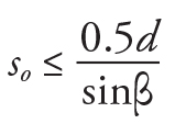
Equation 26
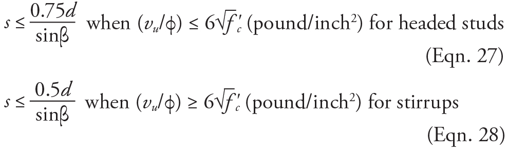
Equations 27-28
The equations presented here are widely used in practice; computer programs are available for the design of headed stud shear reinforcement or stirrups. Program STDESIGN (Decon®)is used here for headed stud shear reinforcement at the interior, edge, and corner columns.
Example 2: Shear reinforcement at an interior column
Design vertical headed studs at an interior column (Figure 2a) based on the following data: column size cx×cy = 12×20 inch2; slab thickness h = 7 inches; concrete cover ct = 0.75 inch; f’c= 4000 pound/inch2; yield strength of studs fyt = 51×103 pound/inch2; flexural reinforcement nominal diameter db = 5⁄8 inch. The factored forces transferred from column to slab are: Vu = 110×103 pound and Muy = 600×103 pound-inch. Computer program STDESIGN gives the solution shown in Figure 4.
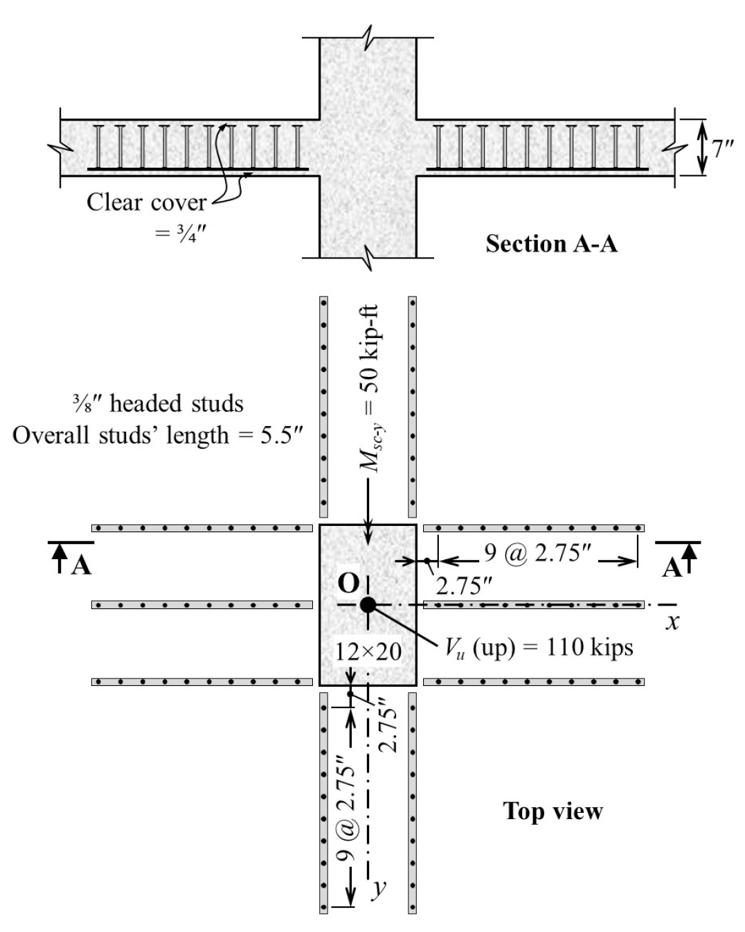
Figure 4. Headed stud arrangement at the interior column of Example 2. All dimensions are in inches.
Example 3: Shear reinforcement at an edge column
Design vertical headed stud shear reinforcement at an edge column (similar to Figure 2b), based on the following data: column cross-section, cx×cy = 18×18 inch2; the values of h, ct, d, f’c, fyt, D, and db in Example 2 apply here. The connection is designed for gravity loads combined with wind load in the positive or negative x-direction. Cases I and II are considered, which produce extreme stresses at Points B and A of the critical section at d/2 from the column or at D and C of the critical section at d/2 from the outermost peripheral line of studs (Figures 5a and 5b). The factored forces, due to gravity load combined with wind load, are given.
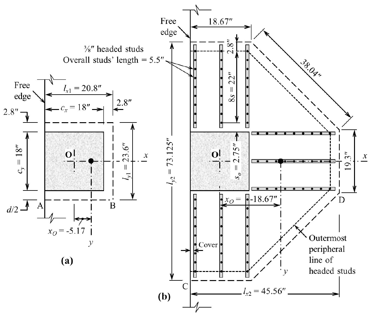
Figure 5. Headed stud arrangement at edge column of Example 3; a) Shear critical section at d/2 from column periphery, b) Shear critical section outside the shear-reinforced zone. All dimensions are in inches.
Case I – Wind load in negative x-direction
Vu = 36×103 pounds; Msc−Oy = 1720×103 pound-inch; Msc−Ox = 0
Case II – Wind load in the positive x-direction
Vu = 10×103 pounds; Msc−Oy = −900×103 pound-inch
Figure 5b shows the headed studs’ arrangement as provided by STDESIGN.
Example 4: Shear reinforcement at a corner column
Design vertical headed stud shear reinforcement at a corner column in Figure 2c for gravity loads combined with wind load in positive or negative x-direction. The dimensions of the column are cx = cy = 20 inches (Figure 6a). The same values of h, ct, d, f’c, fyt, D, and db in Example 2 apply here. Two cases (I and II) are considered, producing extreme shear stresses at Points A and B of the critical section at d/2 from the column or at C and D of the critical section at d/2 from the outermost peripheral line of studs (Figures 6a and 6b). The factored forces, due to gravity loads combined with wind load are:
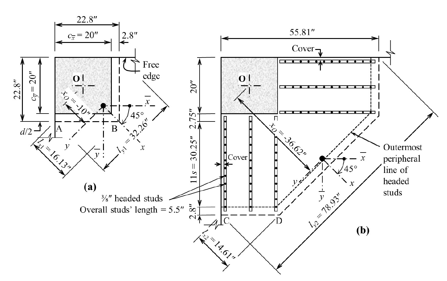
Figure 6. Headed stud arrangement at corner column of Example 4; a) Shear critical section at d/2 from column periphery, b) Shear critical section outside the shear-reinforced zone. All dimensions are in inches.
Case I – Wind load in positive x-direction
Vu = 6×10³ pound; Msc−Oy = 338×103 pound-inch;
Msc−Ox = 238×103 pound-inch
Case II – Wind load in negative x-direction
Vu = 22×103 pounds; Msc−Oy = 953×103 pound-inch;
Msc−Oy = 377×103 pound-inch
Figure 6b shows the headed studs’ arrangement as provided by STDESIGN.
Notation
Ac = area of shear critical section
Av = area of shear reinforcement on one peripheral line parallel to perimeter of column section
bo = length of perimeter of shear critical section
c = side of a square column
D = stem diameter of stud shear reinforcement
d = effective depth of slab; average of distances from extreme compression fiber to centroids of tensile reinforcements running in two orthogonal directions
f’c, fy, and fyt = specified concrete compressive strength and yield strength of flexural and shear reinforcements
h = slab thickness
Ix, Iy = moments of inertia of shear critical section about x and y axes, respectively
Ixy = product of inertia of shear critical section
Jx, Jy = property of the shear critical section = d times (Ix or Iy)
ls = length of a segment of the shear-critical section
lx, ly = projections of shear critical section in the x- and y-direction, respectively
Msc-x, Msc-y = moment transferred between slab and column about x– or y-axis, respectively
s = spacing between peripheral lines of shear reinforcement
so = spacing between first peripheral line of shear reinforcement and column face
Vflex = shearing force that develops local flexural yield-line mechanism
Vu = factored shear force
vc = nominal shear strength provided by concrete
vn = nominal shear strength at the perimeter of the shear-critical section
vs = nominal shear strength provided by shear reinforcement
vu = shear stress due to factored load, or largest absolute value of vu
x, y = coordinates of point on perimeter of shear critical section with respect to centroidal principal axes x and y
x, y = coordinates of point on perimeter of shear critical section with respect to centroidal non-principal axes x and y
β = slope of inclined shear reinforcement with the slab surface
γvx, γvy = fractions of moment transferred by shear eccentricity – between slab and column – about x– or y-axis, respectively
λ = modification factor reflecting reduced mechanical properties of light-weight concrete, all relative to normal-weight concrete of the same compressive strength
ρ, ρ’ = reinforcement ratio of flexural reinforcement at bottom and top, respectively
ρ’min = minimum top flexural reinforcement above support to avoid flexure-induced punching
ϕ = strength reduction factor
ϕflex = flexural strength reduction factor