
Part 1: Seismic Drift
This article provides an overview of the Provisions in ASCE 7-16, Minimum Design Loads for Buildings and Other Structures, for the determination of seismic drift. The article covers several factors of drift computations, including the fundamental period, scaling modal drift obtained from modal response spectrum analysis, the seismic design base shear, torsional irregularities in structures, and the significance of P-delta effects. It also addresses the effects of elastic lateral deflections of the floor plate, and how to account for inelastic drift of a structure using a deflection amplification factor, and the allowable drifts for different types of seismic forces resisting systems and the risk categories. All section references and equation numbering are from ASCE 7-16.
Fundamental Period
The fundamental period of a structure is the main parameter affecting building displacement. The fundamental period used to obtain loading for seismic drift calculations may be either the calculated approximate fundamental period per Section 12.8.2.1 or the calculated actual period from modal analysis. The fundamental period obtained from modal analysis is permitted to exceed the product of the coefficient for the upper limit on the calculated period (Cu) from Table 12.8-1 and the approximate fundamental period, Ta, determined in accordance with Section 12.8.2.1. The elimination of the period upper limit, TaCu, for drift determination is intended to avoid the overestimation of displacement because of the inconsistency between forces and computed fundamental period.
Scaling
Determination of drift resulting from modal response spectrum analysis is, to some extent, similar to the equivalent lateral force determined by a statics analysis procedure. The primary difference is that the periods and displacements are known for several modes of natural vibration and combined using one of the recognized combination methods to obtain the final story displacements. Also, if the base shear calculated in modal analysis (Vt) is less than base shear (V) as calculated by the equivalent lateral force (ELF) procedure, then the story drifts must be scaled up and drifts are multiplied by CsW/Vt. Note that the scaling is only required if the minimum seismic response coefficient controls the base shear, Cs = 0.5 S1/(R/Ie) (Eq. 12.8-6). Modal drift need not be scaled in all other situations. The reason for the scaling requirement is to be consistent with the requirements for design based on the ELF procedure.
Story Shear Force
Seismic design forces, starting with ASCE 7-10 and onward, have been obtained from the code as strength level forces, and drift compliance with allowable drift limits is also computed at strength level forces. However, the design earthquake forces for checking drift may be lower than the forces used for strength design due to the exemption of minimum base shear obtained from V = 0.044SDSIW ≥ 0.01W, and because the fundamental period is not restricted to the upper limit TaCu which results in lower shear forces.
The Cs exemption is especially important for tall buildings that are typically drift-controlled rather than strength-controlled. However, for structures in high seismic regions where S1 is equal to or greater than 0.6g, ASCE 7-16 requires that the minimum base shear controlled by Cs= 0.5 S1/(R/Ie) (Eq. 12.8-6) be used for the drift determination because it accounts for large displacement of structures.
Elastic Displacement
An important aspect of drift analysis is the application of vertical loading during analysis. The inclusion of gravity loads is to maintain consistency between the forces used in drift analysis and stability verification (P – Δ). The gravity load and seismic load combination used in drift analysis is stated in Load Combination 6, Section 2.3.6 of ASCE 7-16: (D+Ev+Eh+0.5L+0.2S). The live load L is permitted to equal 1.0L for occupancies where the live load is more than 100 psf (4.78 kN/m2). Note that allowable load design combinations use strength level seismic load, as indicated in Section 12.8.6 of ASCE 7-16.
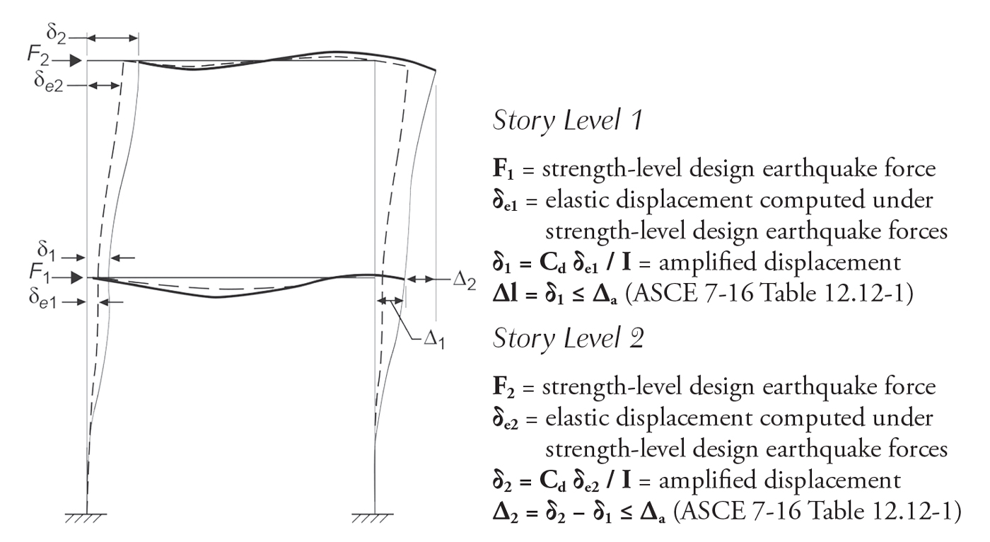
Figure 1. Story drift determination (ASCE 7-16 Figure 12.8-2).
The elastic displacement is the absolute lateral displacement of any point in the structure relative to its base under strength-level design earthquake forces. The story drift is calculated as the relative elastic displacement of a story to the story below, as shown in Figure 1. However, the points for this comparison vary depending on the following:
- For a structure where centers of mass align, the story drift is computed based on the center of mass displacements.
- For a structure where centers of mass do not align (more than 5% eccentricity between the center of mass), the story drift may be computed based on a vertical projection of the center of mass of the upper story to the lower story, and relative displacement of the projected point used.
- For structures in Seismic Category C, D, E, or F with horizontal irregularity 1a or 1b, the story drift is computed based on the largest difference of aligned points at the edge of the structure.
Inelastic Displacement of Structure
Inelastic displacement is the actual displacement, obtained by elastic analysis multiplied by a deflection amplification factor, Cd, chosen from Table 12.2-1 based on the type of seismic force resisting system. The inelastic displacement is obtained from the following equation:
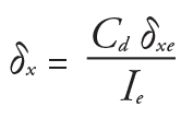
where:
δx : Inelastic Displacement
δxe: Elastic Displacement
Cd: Deflection Amplification Factor in Table 12.2-1 of ASCE 7-16
Ie: Importance Factor determined in accordance with Section 11.5.1 of ASCE 7-16
As illustrated in Figure 2, the deflection amplification factor, Cd, accounts for the increase in displacement due to the inelastic response of a structure that is not determined by elastic analysis and corrects for the reduction of forces introduced by response modification factor R.
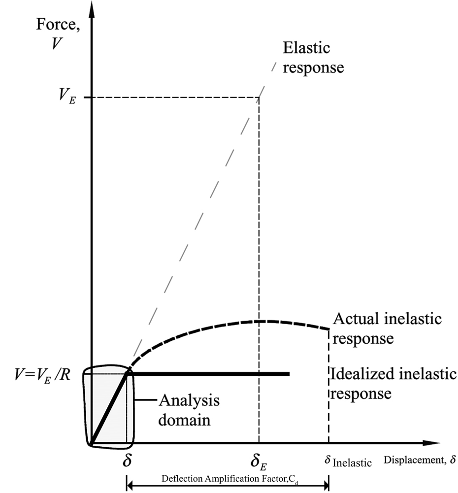
Figure 2. Displacement used to compute drift (NEHRP Recommended Seismic Provisions for New Buildings and Other Structures, FEMA P-1050-1/2015 Edition).
If a structure remains elastic during an earthquake, the forces developed in the building are elastic (not reduced by R) which results in elastic displacements that do not account for system ductility and overstrength. If a structure is inelastic with initial stiffness equal to that of an elastic structure, then its maximum displacement will be similar to that of an elastic system. On the other hand, structures having shorter fundamental periods are characterized by inelastic drifts larger than elastic drifts of structures of similar initial stiffness.
The deflection amplification factors values set in Table 12.2-1 may underestimate the inelastic drift, especially for seismic forces resisting systems that have Cd value less than the R-value. A research paper, Deflection Amplification Factor for Seismic Design Provisions, concluded that the deflection amplification factors (Cd) in the code are non-conservative and, to accurately capture the inelastic drift of system, the value of Cd shall be set equal to the value of R.
Allowable Drift Limits
The allowable drift limits placed by ASCE 7-16, as shown in Table 1, are functions of the risk category and type of seismic forces resisting system. The allowable drift limits, Δa, for moment frame systems assigned to D, E, or F seismic design category are divided by the redundancy factor, ρ, since they are governed by drift considerations per Section 12.12.1.1 of ASCE 7-16.
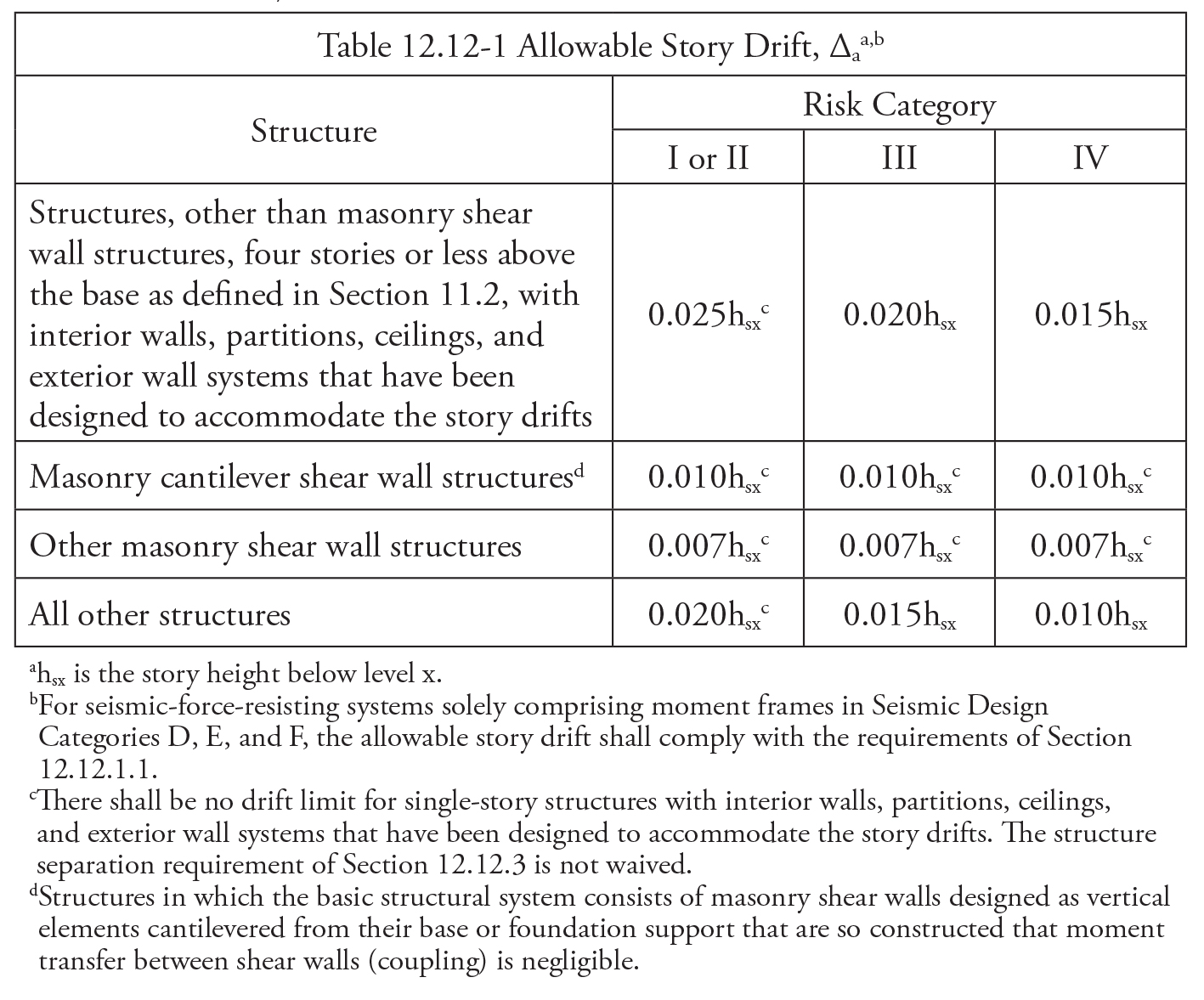
Table 1. Allowable Story Drift (ASCE 7-16).
The allowable drift of other structures with Risk Category I and II is approximately 10 times the allowable drift under wind forces. Risk Category III and IV structures have more stringent drift limits to ensure better performance of the structure and serviceability after a seismic event.
Torsional Irregularity and Drift
Torsional irregularities affect the structure’s drift and must be considered for buildings with diaphragms that are not flexible. The applicability varies depending on the type of horizontal irregularities that occur and the seismic design category. While the inherent torsion must be applied in all cases, accidental torsion does not; it must only be applied for drift of buildings under certain combinations of seismic category and irregularity. However, it does need to be applied in all cases to determine if horizontal irregularity exists. Furthermore, a specific subset of structures must also account for amplification of accidental torsion. Accidental torsion and amplification considerations for drift are as follows:
- For structures assigned to Seismic Category B with Type 1b horizontal structural irregularity, accidental torsion must be applied. However, torsion amplification is not required.
- For structures assigned to Seismic Category C, D, E, and F with Type 1a or Type 1b horizontal structural irregularity, the accidental torsion with amplification must be applied.
Drift and P-Delta Effects
P-delta effects must be considered, per Section 12.8.7 of ASCE 7-16, when the stability coefficient per Equation 12.8-16 and 12.8-17 is more than 0.10. Where the design story drift is obtained from first order analysis, it should be increased by an incremental factor Ad, or a P–Δ analysis shall be conducted to obtain the second-order drift. The incremental factor accounts for the increase in the drift from applied vertical loads on the displaced structure leading to another increment of story drift. The incremental factor can be computed from the following equation:
Incremental factor (Ad) = 1 / (1-θ)
where θ is the stability coefficient and is determined as follows:
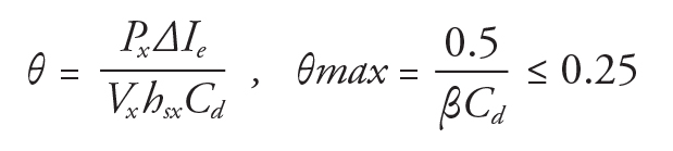
The final story drift when considering the P-delta effect is calculated as follows:
Final story drift, Δ = (Ad) (Δinitial) = (1 / (1- θ)) (Δinitial)
Δinitial is the inelastic design story drift obtained from first order analysis as defined in Section 12.8.6 of ASCE 7-16.
Another essential point is that the story shear (Vx) and the design drift (Δ) used in stability coefficient equation are required to be those occurring simultaneously without restriction to the upper limit of the fundamental period, TaCu.
Conclusion
In addition to the factors that affect drift mentioned above, seismic drift is also sensitive to additional parameters such as the type of soil-structure interaction and effective moment of inertia for the reinforced concrete frame. All of the factors affecting the drift should be thoroughly addressed because seismic drift criteria is one of the governing factors in the selection of the proper lateral structural system. ASCE 7-16 provisions regarding drift evaluation aim to ensure the acceptable performance of structures by limiting drift. This results in understanding the structural performance of member inelastic strain, system stability, and vulnerability of nonstructural elements. Buildings subject to earthquakes need drift control to limit damage to partitions, glass, and other fragile nonstructural components.■
References
ASCE 7-16, Minimum Design Loads For Buildings and Other Structures. American Society of Civil Engineers, Reston, VA.
Ghosh, S.K., and Henry, J., 2009 Handbook: Structural Provisions, International Code Council Series. ICC 2009, Chicago, IL.
International Building Code, 2006 Edition. (2007). ICC, Country Club Hills, IL. NIST, 2016. NEHRP Seismic design of reinforced concrete special moment frames: A guide for practicing engineers, Second Edition, GCR 16-917-40, NEHRP Seismic Design Technical Brief No. 1, produced by the Applied Technology Council and the Consortium of Universities for Research in Earthquake Engineering for the National Institute of Standards and Technology, Gaithersburg, MD.
FEMA P-1050, 2015 NEHRP Recommended Seismic Provisions for New Buildings and Other Structures. Volume I: Part 1 Provisions, Part 2 Commentary. National Institute of Building Sciences, Building Seismic Safety Council, Washington, D.C. 20005, 2015.
FEMA P-1051, 2015 NEHRP Recommended Seismic Provisions: Design Examples. National Institute of Building Sciences, Building Seismic Safety Council, Washington, D.C. 20005, July 2016.
Uang, C., and Maarouf, A. (1994). Deflection Amplification Factor for Seismic Design Provisions. Journal of Structural Engineering, 120(8), pp.2423-2436.