
A Simple, Serviceable, and Safe Option
There are three fundamentally different methods to design a post-tensioned concrete member: load balancing, rigorous, and straight. All three methods, when followed correctly, result in serviceable and safe members. They differ substantially, however, both in the computational effort and potentially in the economy of the final design.
The application of each method depends on the extent of the project, the expectations of the client, and the expertise of the design engineer.
Engineers who specialize in post-tensioning design and who are comfortable with large and complex projects benefit most from the rigorous method. The additional time and effort expended when using this method are offset by the economy in design.
Design Options
Most post-tensioned concrete buildings are designed using the load-balancing method. While simple and intuitive, it requires the computation of hyperstatic (secondary) moments – a somewhat unfamiliar concept for many engineers. Engineers who do not routinely design post-tensioning tend to pass the design to those specialized in the field. The rigorous method is detailed. It provides a closer picture of the member’s response to post-tensioning, as opposed to merely meeting the code-specified requirements of serviceability and safety. It applies where more reliable deformation, cracking, and post-cracking information of the member are sought.
It is not uncommon that a designer may have to verify the adequacy of a post-tensioned member or design of a couple of the members of the project with post-tensioning. In this case, the optimization of the post-tensioned members will have little impact on the overall economy of the project. For these applications, the straight method is preferred. The straight method relies on the knowledge and tools that structural engineers commonly use, instead of the unique, rigorous method.
Load Balancing
Basic load balancing, introduced by T. Y. Lin in the early 1960s and extended to non-prismatic members by the author, has led to increased application of post-tensioning in building construction. The load-balancing method did away with the complexity of post-tensioning design, which hindered its widespread adoption by structural engineers.
The load-balancing method relies on the common knowledge and daily practice of consulting engineers except for the recognition and explicit computation of hyperstatic moments from post-tensioning. The computation and inclusion of the hyperstatic moments are necessary for the safety compliance of the member. The understanding and treatment of the hyperstatic effects is generally an obstacle for many structural engineers.

Figure 1. Contribution of post-tensioning in the reduction of the effect of dead load on the member.
Figure 1 illustrates the concept in its basic form. The tendon shown in part (a) is in the shape of a simple parabola in each span. Pulled to force P, the tendon exerts a uniform uplift (PT) shown in part (b). The uplift can be considered to reduce the effect of the dead load of the structure (DL), to (DL-PT) shown in part (c) of the figure.
For deflection, stresses, and crack control, which are part of the serviceability check of the member, the effective downward force on the member is reduced by the PT force. This improves the service performance of the member.
The service load combination for “total load” is:
U = 1.00DL + 1.00PT + 1.00LL (Eqn. 1)
At ultimate limit state (ULS), the member relies on the contribution of the tendons in resisting the demand forces. Hence the member shown in Figure 1c – with missing tendons – would not qualify. Placing the tendon back in the member to provide resistance, the configuration and load condition shown in Figure 1d applies.
Flexing of the member under the tendon force, coupled with the restraint of the supports to the member’s unrestricted flexing, result in the reactions R at the supports (Figure 2). The reactions are generated when the member is not free to change its shape. Hence, “hyperstatic” reactions – also referred to as secondary reactions.

Figure 2. Hyperstatic reactions from post-tensioning.
The hyperstatic reactions (R) result in forces in the member, such as moments, that must be resisted by the post-tensioning tendons shown and possibly by adding mild-steel reinforcing bars.
For the safety of the structure at ULS, using ACI 318-14, Building Code Requirements for Structural Concrete and Commentary, the primary load combination is:
U = 1.20DL + 1.60LL + 1.00HYP (Eqn. 2)
Concrete and prestressing tendons provide the resistance to the force demand. The shortfall in resistance, if any, is met by adding nonprestressed reinforcement.
In summary, (i) tendon is viewed removed to check the service condition; (ii) tendon is in place acting as reinforcement to check the safety condition.
Rigorous Method
In the rigorous method, unlike the load-balancing method, the prestressing steel is not considered as removed from the member. The prestressing steel is treated the same as nonprestressed reinforcement, but with an initial stress.

Figure 3. Comparison between load balancing and rigorous modeling methods. The sub-images on the left represent the Load Balancing Method, where prestressing is viewed as applied load. The sub-images on the right represent the Rigorous Method, where the prestressing steel is considered as reinforcement with initial stress.
Figure 3 highlights the features of the rigorous method and its comparison with the load-balancing method. It is a partial view of a post-tensioned member, subdivided into finite elements.
The sub-figures on the left (b, d, and f) represent the load-balancing method applied to a segment of the member. The prestressing tendon is removed and is replaced by the forces that it exerted when in place (b and d). At the application of load, and lapse of time, the member deforms (f). In a detailed analysis, the stresses in the deformed condition must be fine-tuned to account for losses in prestressing and change in dimensions of the segment from creep, shrinkage, and other stresses.
The sub-figures on the right (c, e, and g) represent the rigorous method. Tendons are initialized with forces at stressing (P). Nonprestressed basic reinforcement, if any, is initialized with zero stress.
The solution shown in Figure 3g is the result of the application of load, and lapse of time, with due allowance for loss of stress in prestressing, creep, and shrinkage of concrete. The solution for the given time and load reflects the instantaneous and long-term effects of prestressing and concrete. The necessity of post-solution computation of long-term losses and their allowance – as is the case in the load-balancing method – does not arise.
The breakdown of the solution at any stage into contributions from dead, live, prestressing, creep, and shrinkage provides the necessary information for the serviceability and safety load combinations of the member.
Figure 4 shows a typical finite element flat shell for slab design using the rigorous method. The element contains the prestressing tendon and nonprestressed reinforcement if any.
Other significant features to the rigorous method include:
- For non-prismatic members, such as members with a change in thickness or step, the computation of balanced loads (forces from prestressing) in the load balancing method is complex and laborious. At each change in location of a member’s centroid, special treatment is required through the addition of local moments. In the rigorous method, the necessity of special treatment at changes in the cross-sectional geometry of the member does not arise.
- The nonprestressed reinforcement in its actual size and position can be specified as part of the analysis model. For rigorous deflection calculation, it is not necessary to substitute the reinforcement by its equivalent area in concrete to correct the member’s stiffness.
- Cracked deflections can be computed with authenticity. The presence of prestressed and nonprestressed reinforcement in amount, location, and orientation included in the computational model (Figure 4) enables more realistic prediction of crack depth and the reduced stiffness necessary for the estimate of cracked deflection.
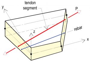
Figure 4. Flat shell finite element showing the inclusion of prestressing tendon and rebar within the element. Tendon segment within the element is initialized with prestressing force P.

The necessity of computing hyperstatic actions from prestressing and including them in the ULS load combination remains as in the load-balancing method.
The “total” load combination for service condition is:
U = 1.00DL* + 1.00LL (Eqn. 3)
Note that, in this case, post-tensioning is an integral part of the structure similar to concrete. DL* includes the effects of post-tensioning. For this reason, it does not appear explicitly in the load combination.
For safety, ACI 318-14 gives the dead load and hyperstatic effects of post-tensioning, each with a different load factor. For this reason, the rigorous solution must be broken into parts. The contribution of post-tensioning must be extracted and deducted from the solution to arrive at the dead load values.
U = 1.20DL + 1.60LL + 1.00HYP (Eqn. 4)
It is noteworthy that, in the rigorous method, the hyperstatic components of creep and shrinkage are of the same category as hyperstatic moments from prestressing. These are available as part of the solution. They impact the force demand for the load combination at ULS. ACI 318 does not require their inclusion in the load combination, however.
Straight Method
In the straight method, the post-tensioning tendons are assumed removed from the member. The tendons are replaced by their uplift effect (balanced load) on the member.
The straight method accounts for the contribution of uplift from prestressing in-service condition, identically to that of the load-balancing method. For the safety condition, however, the contribution of post-tensioning is handled differently.
The straight method does not require to compute and account for the hyperstatic actions from prestressing as a separate design step. This is advantageous for engineers who do not deal with post-tensioning regularly and may not be conversant with the computation of hyperstatic actions.
The load combination for the “total” service condition is the same as the other two design methods, namely:
U = 1.00DL + 1.00LL + 1.00PT (Eqn. 5)
(In this load combination, “total load” is considered. The coefficient LL depends on the code case, but that of PT remains equal to 1.00.)
For ULS, post-tensioning is viewed as an externally applied load, similar to the service condition (Figure 5). Unlike the previous two methods, the post-tensioning tendons are not considered reinforcement for providing resistance to the applied load. The entire resistance to the “computed” design moment, if any, is provided by nonprestressed reinforcement, along with compression from prestressing (Figure 5).

Figure 5. Ultimate limit state (ULS) load diagram using the straight method.
In this case, the load combination for the ULS is:
U = 1.2DL + 1.6LL + 1.00PT (Eqn. 6)
In the above load combination, PT is substituted for HYP (hyperstatic) when compared with the other two methods. The value of PT in this load combination is the same as that used for the service condition.
The preceding is complete and valid in arriving at a safe design. It is not the most economical alternative, however. Its simplicity and expediency justify its application where the economy of the member is not of critical concern.
Summary
To summarize, the primary distinguishing features of the three design methods are:
- Load-balancing method:
- Post-tensioning tendons are considered removed from the member for service design.
- Tendons are considered back in the member for safety design.
- Rigorous method
- Tendons are retained in the member for service design.
- Tendons are retained in the member for safety design.
- Straight method
- Tendons are removed from the member for service design.
- Tendons are kept out of the member for safety design.
Three items enhance the performance and improve the economy of a post-tensioned member. These are (i) uplift, (ii) precompression, and (iii) gain in tendon stress at ultimate limit state, compared to service condition.
The first two design methods take advantage of all three enhancements.
The straight method, in its simplest form, takes advantage of the tendon uplift only. Allowing for precompression at ULS improves the economy of this design option. The method does not benefit from the gain in tendon stress at ULS, however.
The straight method is safe and expeditious. It eliminates the effort of computing the hyperstatic actions from prestressing as a separate design item and its explicit inclusion in design.
At ULS, prestressing steel is stretched beyond its service condition. The stress gain from added tendon stretching, among other factors, depends on whether the tendons are bonded or unbonded. Using ACI-318-14, Section 20.3.2.4.1, the stress gain for bonded tendons can be as much as 60 ksi (414 MPa) and for unbonded tendons up to 30 ksi (207 MPa). Assuming rebar at 60 ksi (414 MPa), the gain in tendon stress translates to mild-steel reinforcement equal to half the cross-sectional area of unbonded tendons and equal to the cross-sectional area of bonded tendons. This is the maximum potential loss in economy of design when using the straight method. Accounting for precompression from prestressing improves the economy of design, however.
The code-mandated provision of minimum nonprestressed rebar in prestressed members reduces the margin of an economic disadvantage when using the straight method.
Where the building code greatly restricts the gain in tendon stress at ULS, the application of load-balancing and rigorous methods lose their advantage. As an example, the European code, Eurocode 2 (2004), limits the stress gain for unbonded tendons at ULS to 100 MPa (14.5 ksi). This is a 9% gain over service condition. The allowed meager gain in stress erodes the advantage of alternative design methods compared to the straight method.■
References
Aalami, B. O. “Structural Modeling of Post-Tensioned Members,” Journal of Structural Engineering, ASCE, Vol. 126, No.2, Feb 2000, pp. 157-162
Aalami, B. O. (1990). Load Balancing – A Comprehensive Solution to Post-Tensioning,” ACI Structural Journal, V. 87, No. 6, November/December 1990, pp. 662-670.
ACI-318 (2014), Building Code Requirements for Structural Concrete and Commentary, American Concrete Institute, Farmington, MI, www.concrete.org, 519 PP; (2014)
EC2, (2004), Eurocode 2: Design of Concrete Structures – Part 1-1 General rules and rules for buildings, European Standard EN 1992-1-1:2004.
Lin, T. Y, “Load-Balancing Method for Design and Analysis of Prestressed Concrete Structures,” ACI Journal Proceedings, V. 60, No. 6, June 1963, pp. 719-742