
Practical Applications and Considerations in Light-Frame Construction
Premanufactured, metal plate-connected, wood drag trusses can provide a pathed load-delivery mechanism designed to assist and engage the lateral force-resisting system (LFRS) elements during high-wind or seismic events.
This article reviews common force transfer considerations in drag trusses and provides suggestions to design professionals for complying with ANSI/TPI 1-2014, National Design Standard for Metal Plate Connected Wood Truss Construction, the truss standard as referenced by the 2015 International Building Code (IBC) which addresses the design criteria for pre-engineered wood trusses. Practical ways to reduce potential failure mechanisms are also discussed.
Background and Applications
A drag truss, sometimes referred to as a “collector” truss, is a single- or multi-ply pre-engineered truss designed to “drag,” distribute, and transfer shear loads generated within the plane of the diaphragm to the vertical LFRS elements.
Common design practice for trussed roof and floor diaphragms in light-frame construction relies on drag trusses to serve as boundary elements (boundary members and their connections) and provide the primary and/or auxiliary load-transfer mechanism configured to carry in-plane axial tension and/or compression forces to the shear walls below.
Intricate building layouts or complex building geometries result in diaphragm irregularities that can result in significant stress concentrations and increased demands at localized boundary element disruptions. Depending upon the increased diaphragm shear demand and building footprint, interior shear walls may need to be engaged. Framing a drag truss over an interior shear wall can help alleviate stress concentrations at diaphragm openings, re-entrant corners, offsets, or reduce the aspect ratio of the diaphragm.
Section 2.3.2.4 of ANSI/TPI 1-2014 sub-sections (a), (b), (c), and (d) require the design professional to provide distinct criteria on construction documents as they relate to drag trusses. As a result, the delegated truss manufacturer requires clear and well-documented plan callouts and details from the design professional. Several common considerations are summarized below.
Common Considerations on Plan
Truss Layout
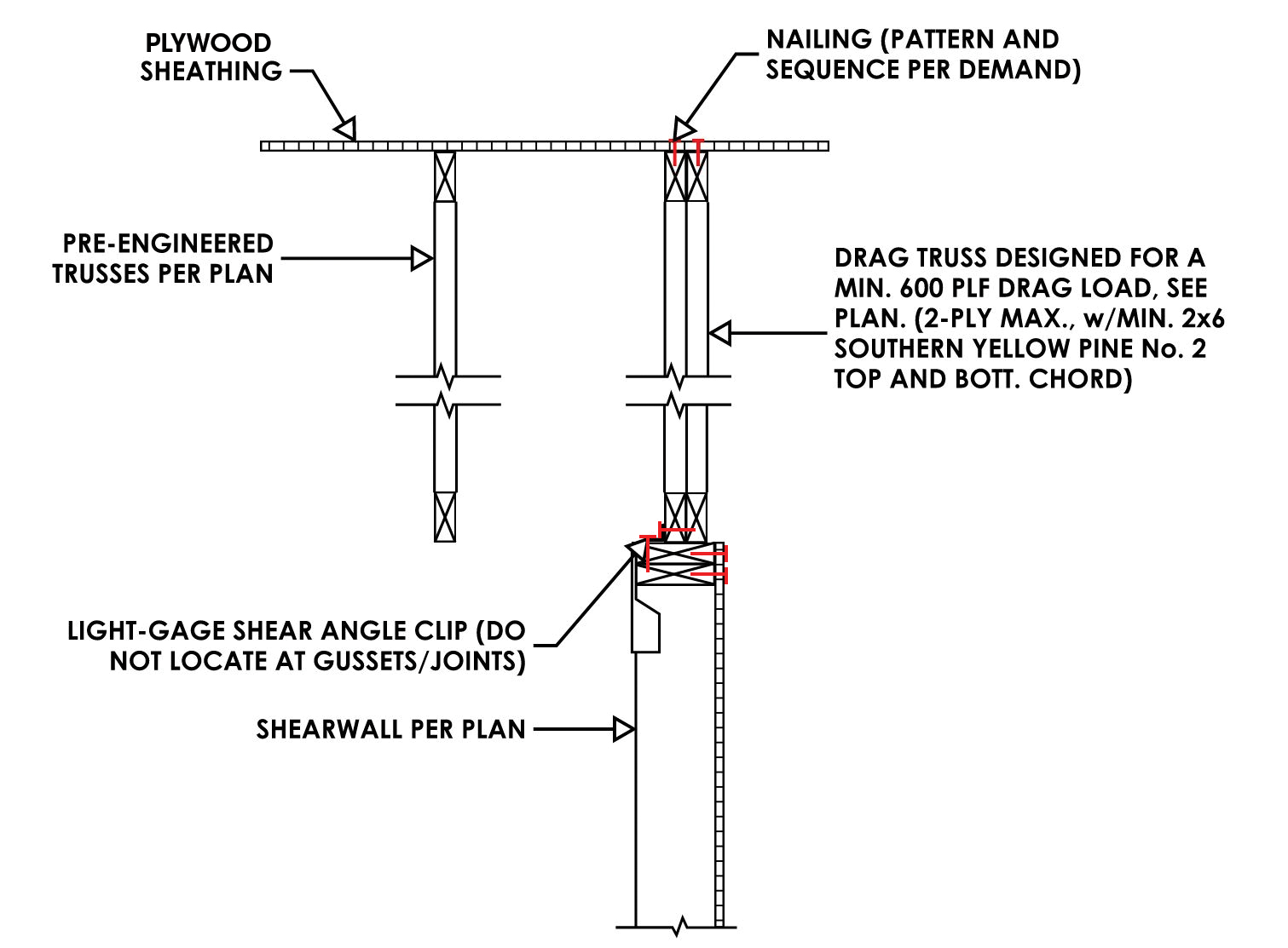
Figure 1. Drag truss parallel to the shear wall below.
The preferred truss layout aligns the drag truss above the vertical LFRS. From a connection standpoint, adding and locating a drag truss directly above the LFRS element (Figure 1) when the typical spacing does not place a truss above the LFRS is the most direct solution and functions equally well for light and heavy shear loads. An alternative load path and connection detail (Figure 2) can be used if the drag trusses and shear wall are not aligned vertically but works better for light shear loads and less well for heavy shear loads.
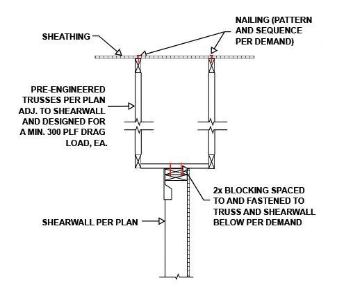
Figure 2. Trusses adjacent to the shear wall below.
Ideally, the drag truss will span the length of and “sit” on the LFRS to develop the lateral and tension/compression overturning forces into the shear wall(s) below. Shear walls that exist under the drag truss, whether partial, sectioned, or full-length, might receive both lateral and gravity forces from the drag truss and can be simultaneously subjected to uplift. In order to ensure a uniform force transfer, the design professional is required, by sub-sections 2.3.2.4 (a), (b), (c) of the truss standard, to furnish and denote the location, orientation, and extent of each drag truss and the connected shear wall(s) below (Figure 3).
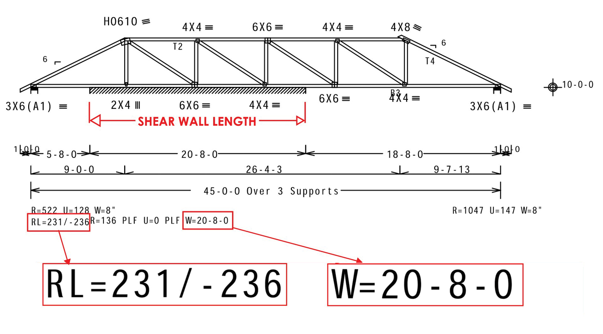
Figure 3. A typical illustration of truss shop drawings showing a drag truss over a shear wall.
A typical truss profile from the truss manufacturer, per Section 2.3.5.5.(f)(7) of the truss standard and IBC 2303.4.1.1(6), is required to show bearing and span conditions on the truss shop drawings. Shop drawings involving drag trusses should be reviewed and scrutinized by the design professional upon receipt.
Truss Drag Force
The drag force, as developed within the plane of the diaphragm sheathing and transferred into the truss, must be called out on the framing plan or in the framing notes for the truss manufacturer. The design professional should provide the magnitude of this force, in units of force per unit length of the sectioned shear wall(s) below (e.g., pounds per linear foot), and note whether it is factored or nominal (unfactored), as stipulated by the applicable code under which the structure is designed.
The loading source – whether wind or seismic – also needs to be noted. The design professional must indicate if the specified loads are reduced (i.e., for ASD 0.6W or 0.7E).
A typical truss profile by the truss manufacturer, per Section 2.3.5.5.(f)(7) of the truss standard and IBC 2303.4.1.1(6), is required to show superimposed drag force loads on the truss shop drawings. The reactions are generally expressed as “RL,” “R,” and “U.” RL is the maximum horizontal reaction in pounds per linear foot from non-gravity loading or drag force loading, R is the maximum vertical reaction from a gravity load case, and U is the maximum uplift reaction from a wind load case (Figure 3).
It should be noted that the truss designer is not responsible for calculating drag force loads in the structure. However, it is the responsibility of the truss designer to understand, review, and incorporate all applicable framing requirements and framing specifications into the design of the truss system. At the request of the design professional or local building official, the truss manufacturer must submit a preliminary truss submittal package to the design professional for review and approval before the manufacturing of the trusses.
Detailing Considerations
The effective strength and stiffness of horizontal wood diaphragms depend primarily on the mechanism of force transfer between adjacent wood structural panels. In-plane unit diaphragm shears are usually limited by the localized load transfer nail capacity in the wood, rather than by the shear capacity of the panels. A drag truss acting as diaphragm support and boundary chord requires boundary nailing stipulation.
Drag trusses interior to a diaphragm will generally receive unit shears from two separate diaphragm spans. Both sequencing and pattern of the nailing must be evaluated.
The staggered nature of the sheathing generally dictates the sequencing. To avoid receiving varying edge and field nailing, special uniform nailing along the full extent of the truss top chord should be shown on both the framing notes and section cut detail.
The nailing pattern is generally dictated by the number of truss plies required to resist the shear demand along the top chord of the drag truss. A single-ply drag truss top and bottom chord may be adequate to handle the axial tension/compression force demanded but inadequate to accommodate the nailing. When this is the case, the design professional can specify to the truss manufacturer the required number of plies, the species, and the minimum size lumber required. The design professional should also review the truss manufacturer’s nail spacing into the drag truss chord to verify that the allowable on-center spacing is not exceeded.
For wind applications, uplift and lateral loads can occur simultaneously. Both uplift and lateral load connection capacities must be evaluated under combined loading and need to consider both loading directions. Light gauge shear angle clips are typically used to transfer the shear from the truss bottom chord to the top of the shear wall. Clip location, however, should not coincide with the metal plate, either the primary plate or the shear plate of the truss joint. Fastening of the clip into a plate can potentially push the plate “teeth” out of the truss bottom chord.
Details should include proper specification of nail sizes (pennyweight, type, diameter, and length), nail spacing, nail-to-panel edge tolerance, and account for the density-dependent capacity of the framing member. Nail withdrawal capacity can be increased with properly fastened ring-shank nails and should be considered by the design professional. Nailing patterns based on species, structural sheathing thickness, and other specified requirements for diaphragms have also been tabulated and are included in the American Wood Council’s (AWC) Special Design Provisions for Wind and Seismic (SDPWS). The design professional should also specify any other tolerance-driven limits.
Bracing and Restraint Considerations
Most wood light-frame construction in low-rise single- or multi-family dwellings have sloped roofs. Where wood structural paneling sheathes and shapes the diaphragm, it also mechanically restrains and braces pitched trusses to provide permanent lateral stability.
Similarly, Section 7.3.3.5 of the truss standard recognizes gypsum board installed directly to the bottom chord of the truss and fastened in accordance with ASTM C840 as an approved continuous lateral restraint and brace mechanism.
Top and bottom chords in compression can buckle laterally if not braced or appropriately reinforced. Truss-framed roof systems with high-pitched top chords and horizontal bottom chords have a smaller weak-axis moment of inertia than, say, a flat roof or floor joists, and under shear load will tend to deflect more in weak-axis bending.
The delegated truss manufacturer is responsible for the bracing that resists in-plane buckling of the individual components of the truss while subjected to compression forces. The design professional, however, is ultimately responsible for the design of the structure and, therefore, needs to confirm that the truss system bracing design has been addressed adequately.
The truss design drawings will indicate, per Section 2.3.5.5(m) and Section 2.3.5.5(o) of the truss standard, which web members require lateral restraint, the maximum axial forces in the truss members, as well as the type and location of the reinforcement. Commonly used types of lumber web reinforcement include scab bracing and T- and L-bracing. Also, the truss manufacturer will provide, within the truss design drawings, the fastening requirements from the reinforcement to the trusses.
Example
The following example shows a common application typical to the nature of a drag truss. Consider a wood-framed, rectangular, single-story family dwelling with a wind-driven uniform distributed loading of 200 plf acting along the diaphragm (Figure 4).
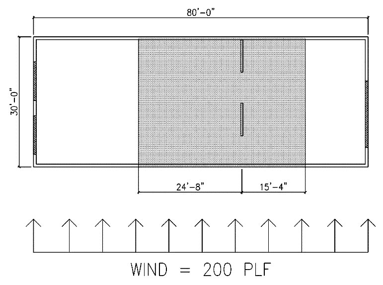
Figure 4. Overall plan view.
The tributary-based unit diaphragm shear of 8 kips is to be transferred along the drag truss and must be called out on the framing plans. Shear walls of 10 feet and 8 feet are sectioned to accommodate for architectural features, which yields approximately 445 plf to be transferred into each shear wall below (Figure 5).
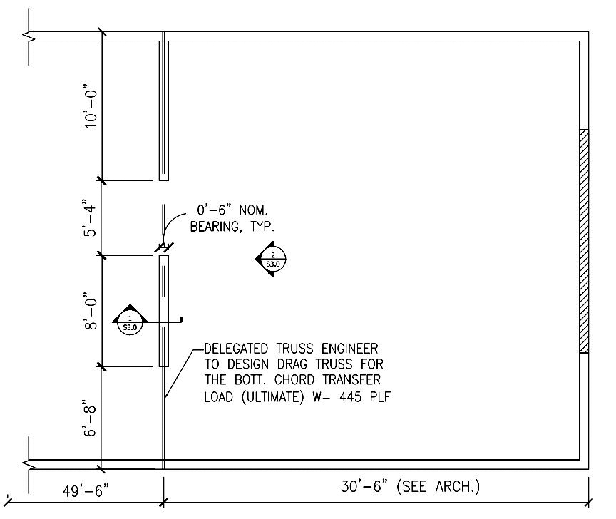
Figure 5. Local plan call-outs.
It should be noted that excessive drift can occur if the aspect ratio of the shear walls underneath the drag truss is not fully evaluated per AWC’s SDPWS.
A plan call-out can be phrased as follows: delegated truss engineer to design drag truss for the bottom chord transfer load (ultimate) due to wind: W = 445 plf. For the condition presented in Figure 5, additional parameters on the plan include the bearing surface width, the location and extent of the truss, and shear walls below.
Summary
This article provides a review of additional considerations required from the design professional for specifying common truss design variables to be used by the truss designer. Proper communication with the truss manufacturer is vital. It is the responsibility of the design professional to specify and detail the design intent and requirements in a clear and unambiguous manner on the construction documents. For more information regarding the design and criteria of metal plate connected wood trusses, the reader is encouraged to read a free, read-only download of the standard ANSI/TPI 1-2014 on the Truss Plate Institute website, www.tpinst.org.■
References
Diekmann, E. F. (1980). Design Details for The Transfer of Forces in Wood Diaphragms to Vertical Elements. Proceedings of a Workshop on Design of Horizontal Wood Diaphragms, 199-251.
Cobeen, K. E., Dolan, J. D., Thompson, D., & Van de Lindt, J. W. (n.d.). Seismic Design of Wood Light-Frame Structural Diaphragms Systems [PDF]. National Institute of Standards and Technology (NIST).
Malone, R. T., & Rice, R. W. Diaphragm Basics. The Analysis of Irregular Shaped Structures: Diaphragms and Shear Walls (pp. 23-82). The McGraw Hill Companies.
Special Design Provisions for Wind and Seismic, American Wood Council, Leesburg, VA.