
Part 1: Two-way Slabs
This article is the first in a series on recommended reinforcement details for cast-in-place concrete construction.
Two-way slabs are generally defined as suspended slabs where the ratio of the long to the short side of a slab panel is 2 or less. In two-way construction, load transfer is by bending in two directions. The main flexural reinforcement usually consists of two mats of reinforcing steel – a top mat and a bottom mat – that run predominately in the directions that are orthogonal and parallel to the rectangular grid of column lines. The bottom mat of reinforcement resists the positive bending moments at the critical sections in the span and is usually continuous over the entire slab area.
The top mat resists the negative bending moments at the critical sections adjacent to the supports in the column strips and middle strips. Guidelines and recommendations on the economical detailing of two-way reinforced concrete slabs are presented in this article.
General Detailing Recommendations
Two-way slabs can be detailed in different ways. One popular method is to call out the top and bottom amounts of reinforcement in the column strip (CS) and middle strip (MS) directly on a plan view of the floor or roof level, as shown in Figure 1 (in the figure, reinforcement is shown in one direction only for clarity; typically, the reinforcement in the perpendicular direction is also shown on the same plan). It is assumed that the bars are uniformly spaced throughout the strip. For design professionals who are not familiar with the economics of reinforced concrete construction, it may be tempting to blindly copy the results from the computer program output directly to the structural drawings without thinking about the consequences of multiple bar sizes and spacing. While this may be adequate in some cases, economy is generally achieved by using the largest size reinforcing bars that satisfy strength and maximum spacing requirements and to repeat bar size and spacing as often as possible. This is illustrated in Figure 1, where #5 bars are used in both the top (T) and bottom (B) layers in the column and middle strips, and the number of bars at similar critical sections are repeated as often as possible.
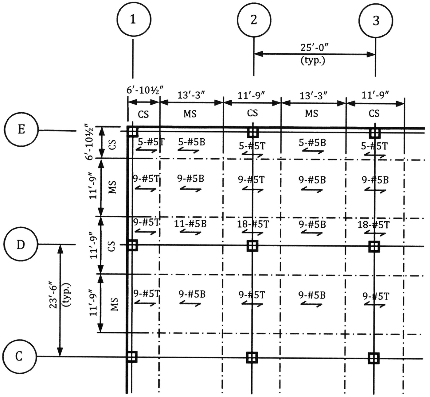
Figure 1. Reinforcing bars indicated on a plan view of the two-way slab system.
In conjunction with the bar callouts in Figure 1, minimum extensions for the top and bottom reinforcing bars in the column and middle strips must be provided. Figure 2 shows the minimum bar extensions given in ACI 318-14, Building Code Requirements for Structural Concrete and Commentary, Figure 8.7.4.1.3a, for two-way slabs without interior column-line beams; included in this figure are the structural integrity requirements in ACI 318-14, Section 8.7.4.2. The bar cutoff points apply to two-way slab systems subjected to the effects from gravity loads only; for systems that are part of the lateral force resisting system, an analysis must be performed to determine the required bar lengths. For simpler detailing, all the top bars in the column strip can be made the same length (0.30ln “or” 0.33ln) instead of having at least half the bars longer than the others. Similarly, it is common for all the bottom bars in the middle strip to be continuous instead of cutting about half of the bars off near the faces of the columns. In general, overall cost savings are achieved by repetition even though more material may be used.
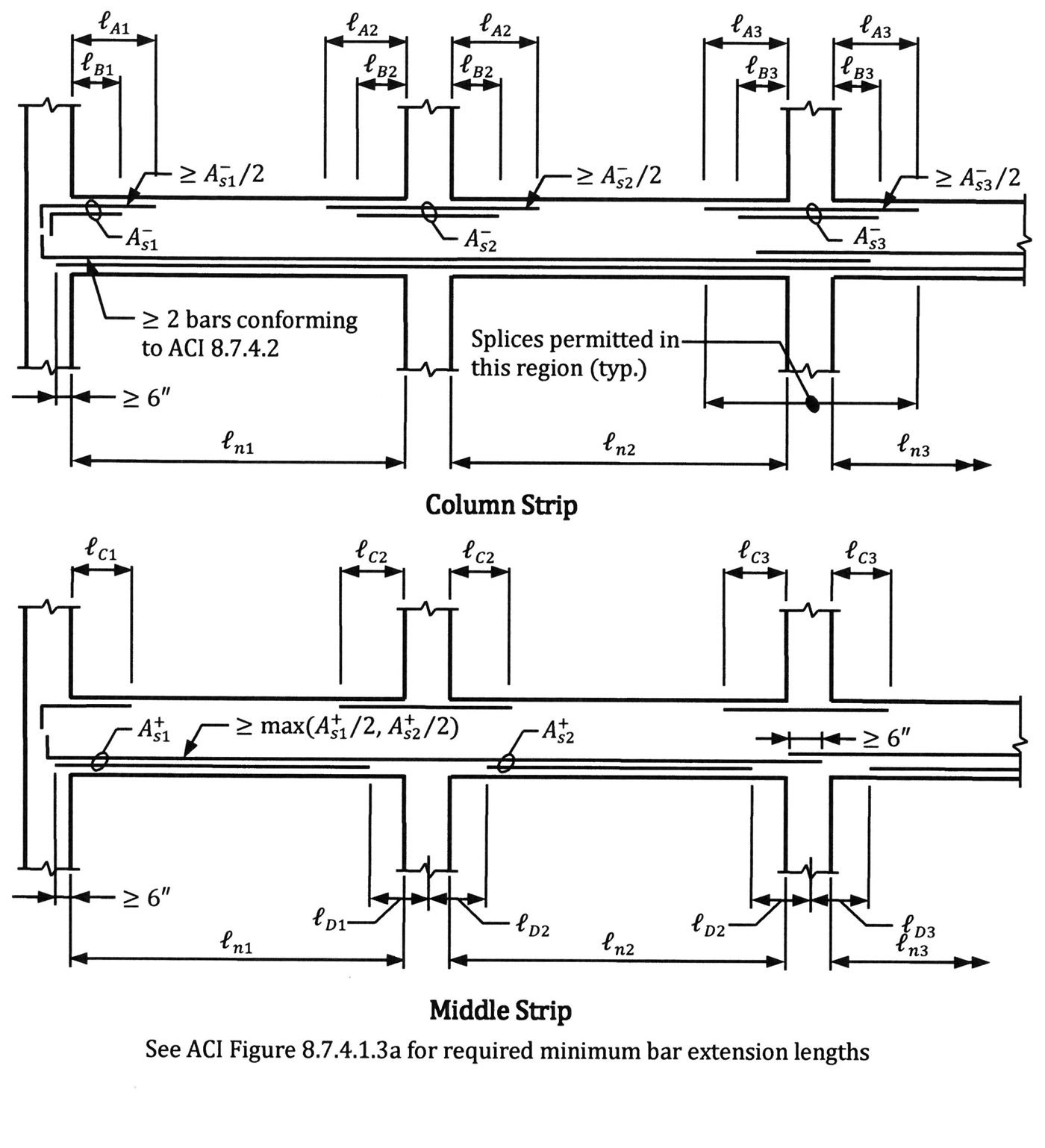
Figure 2. Minimum bars extensions for a two-way slab system.
In lieu of calling out the number and size of reinforcing bars directly on the plan, a bar schedule like the one shown in Figure 3 can be used.
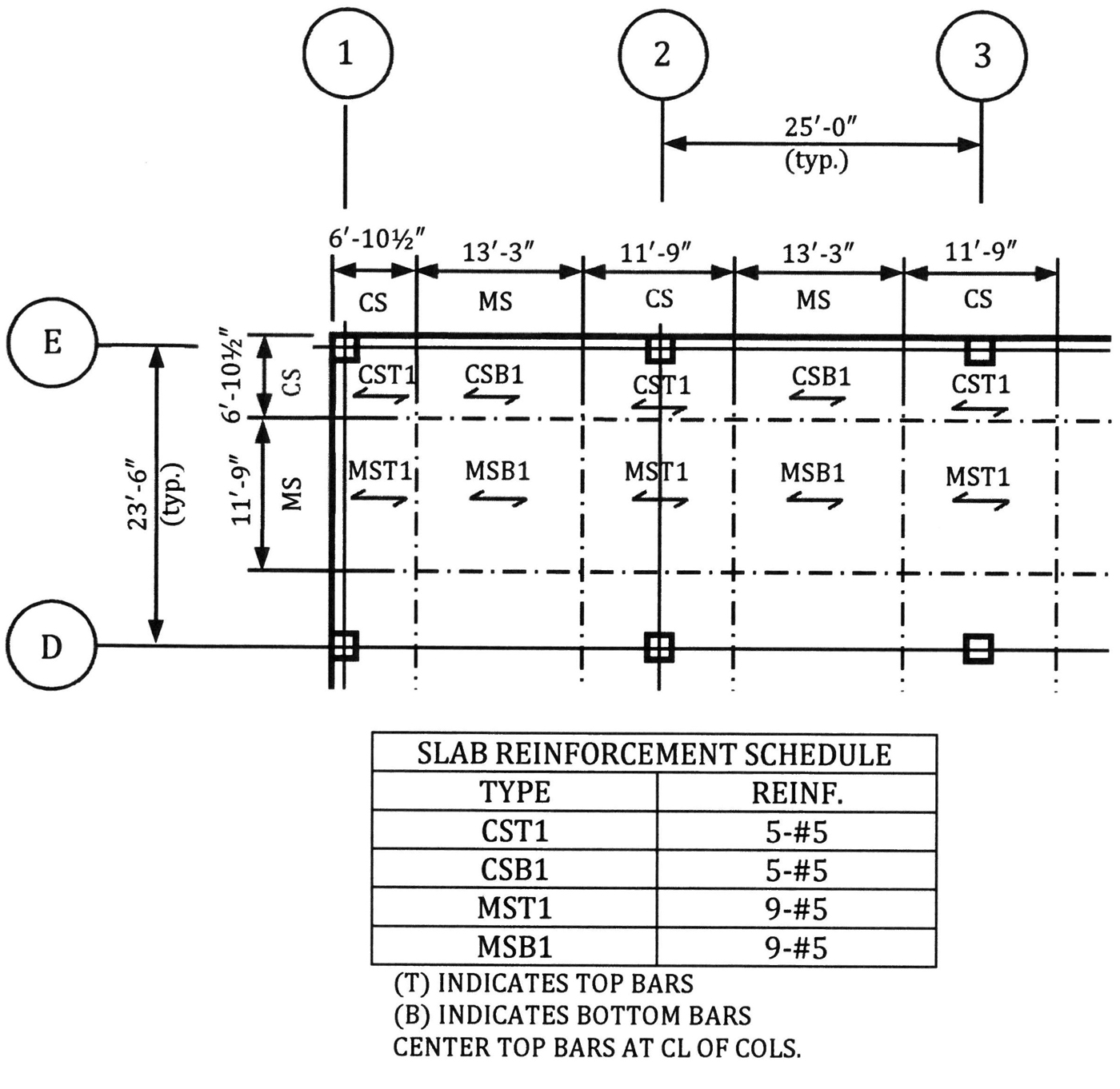
Figure 3. A bar schedule for a two-way slab system.
Another way to call out the reinforcement is to specify uniform top and bottom reinforcement across the whole slab, and to indicate any additional reinforcement that is required at the critical sections in the column and middle strips on the structural drawings; the spacing of these additional bars should be a multiple of that provided for the main bars.
In two-way slab systems without beams, the amount of negative reinforcement at the columns may need to be increased above that required for the negative bending moment at the critical section to satisfy the requirements of ACI 318-14, Section 8.4.2, pertaining to moment transfer at the slab-column joint. This additional reinforcement needs to be clearly documented on the structural drawings. Where required, the additional bars are usually provided in the column strips directly over the column. An example of a detail at an edge column is given in Figure 4. The 4-foot 4-inch dimension in the figure is the effective slab width that resists the transfer moment at the joint.
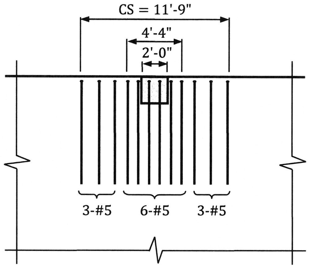
Figure 4. Recommended detail for additional reinforcement due to moment transfer at a slab-column joint.
Regardless of the method that is used to identify the reinforcing bars, it is important to clearly indicate which reinforcing bars are to be placed in the outer and inner layers. Reinforcement in the direction of the larger design moments is usually placed in the outermost layers. Identifying the inner and outer layers of reinforcement can be accomplished by a note or a detail on the structural drawings.
Offset Columns
Where columns are offset in plan, the top and bottom reinforcing bars should be placed orthogonally, if possible, as shown in Figure 5. This minimizes constructability issues compared to skewed bars. Where skewed bars are used, they should be provided in a separate, bottom layer; the top bars should be placed orthogonally. Top bars in the middle strip should be centered on a line connecting the column center lines.

Figure 5. Placement of reinforcement at offset columns.
Two-way Slab Systems with Beams
The location of the top reinforcement in the slab must be clearly indicated on the structural drawings where column-line beams are present. Because the minimum cover to the slab reinforcing bars is usually smaller than that of the beam reinforcing bars, the slab bars are typically placed above the top bars in the beam and in the same plane as the beam stirrups (Figure 6).
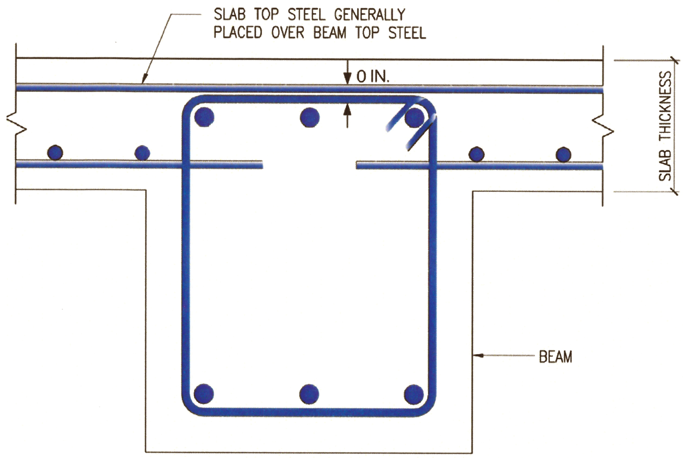
Figure 6. Placement of reinforcement at column-line beams.
Corner Reinforcement
ACI 318-14, Section 8.7.3, addresses exterior corners of slabs that are supported by stiff elements such as walls and edge beams. These stiff elements restrain the slab and cause additional bending moments at the exterior corners. Corner reinforcement must be provided in the top and bottom of the slab to resist these bending moments. According to ACI 318-14, Section 8.7.3.1.3, reinforcement must be placed parallel to the diagonal in the top of the slab and perpendicular to the diagonal in the bottom of the slab (Figure 7). Reinforcement parallel to the slab edges is permitted to be used instead of the diagonal bars. This layout is preferred because of ease of constructability.
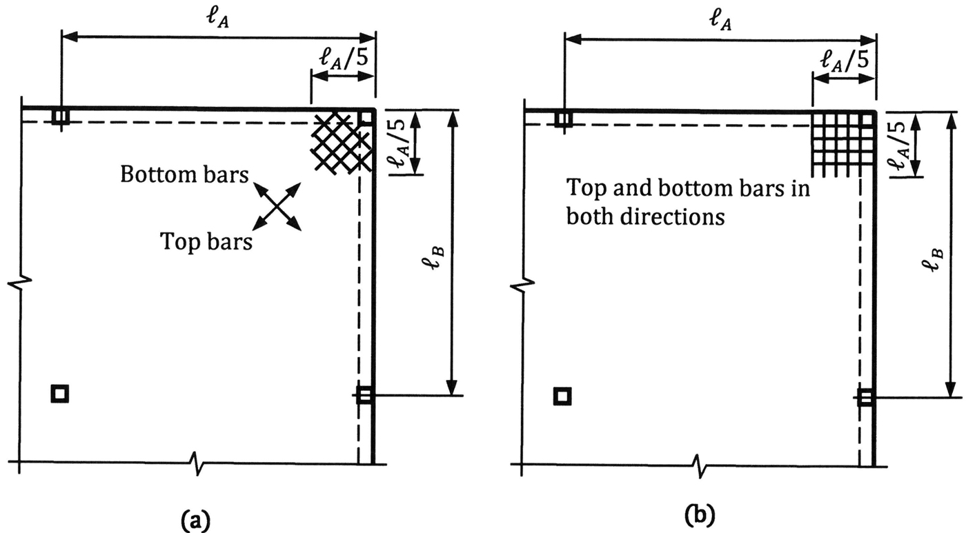
Figure 7. Required reinforcement at slab corners supported by stiff edge members: a) Reinforcement parallel and perpendicular to the diagonal; b) Reinforcement parallel to the slab edges.
Drip Grooves
Drip grooves or drip edges along the edge of a slab soffit can cause issues related to the required cover to the longitudinal reinforcement. These grooves are usually formed using a form chamfer strip or a one-inch piece of dimensional lumber nailed to the formwork deck near the slab edge. The two ways to maintain required concrete cover are shown in Figure 8: (a) offset the bars crossing the groove, and (b) relocate the transverse and longitudinal layers of reinforcement so that the affected reinforcing bar (shown as a circle in the figure) is moved away from the groove, thereby maintaining the required cover.
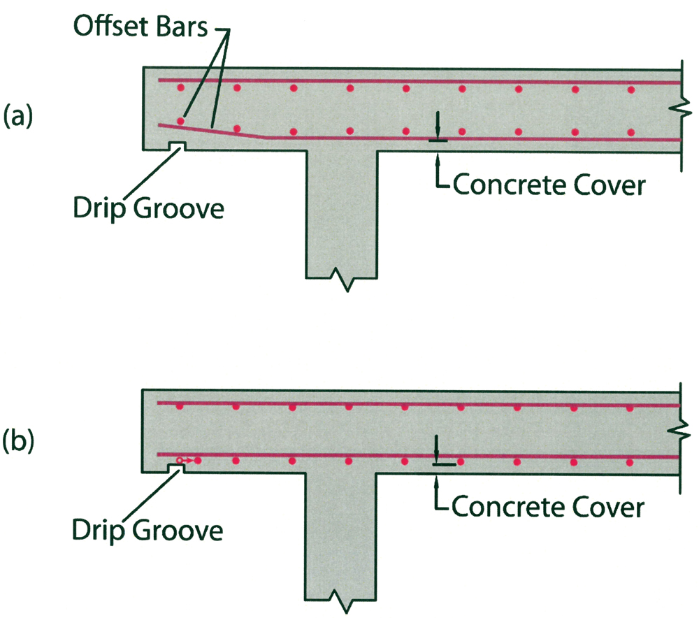
Figure 8. Slab with drip groove at the edge of soffit: a) Cover maintained by offsetting the bottom longitudinal reinforcing bars;
b) Cover maintained by relocating longitudinal reinforcing bars.
Additional information on economical detailing of two-way slab systems can be found in the CRSI publication, Design Guide for Economical Reinforced Concrete Structures.■
References
ACI (American Concrete Institute). 2014. Building Code Requirements for Structural Concrete and Commentary. ACI 318-14, Farmington Hills, Michigan.
CRSI (Concrete Reinforcing Steel Institute). 2015. Reinforcing Bar Detailing. Schaumburg, IL.
CRSI (Concrete Reinforcing Steel Institute). 2016. Design Guide for Economical Reinforced Concrete Structures. Schaumburg, IL.