
The landmark Gothic-Revival massive granite towers of the Brooklyn Bridge, with their arrays of cable-and-stay structural scheme, developed in the usual way for its era. Commercial East River shipping and ferry operators in the 1860s protested when they foresaw that if the East River Bridge in New York City, proposed by John Roebling (b.1806), was built, it would undercut their highly profitable river businesses. The flourishing river interests organized and put political pressure on the War Department to thwart the proposal.
Concurrently, a hard freeze of the East River in 1866-7 shut down all waterway transport, demonstrating the economic advantages of a bridge. In resolving the case in 1869, a Federal ruling stipulated that any future East River bridge constructed could not interfere with surface river traffic, no pier components could extend beyond pier vertical edges, and the deck must be raised to 135 feet above mean high water. The Roebling office, aided by architect William Hildenbrand, made the required minor design changes to proceed with the nearly 6,000- foot-long suspension bridge. The 1597-foot-long center span is flanked by two 930-foot-long side-spans, with the approaches making up the difference in length.
Roebling died in mid-1869, leaving design drawings complete for the world’s longest span bridge (completed 1883) with its great tonnages of granite and limestone, and the nation’s first use of nascent galvanized crucible steel cable wire in a bridge (SEAoNY.org\publications V22, N3. 2017). His son, Washington Roebling (b.1837), was appointed later that year as Engineer-in-Chief to build the bridge.
Soils, Masonry Tower Foundations
The stable sub-foundations are of high bearing-quality on solid strata. At the Brooklyn tower, 1860s borings established gneiss at elevation -97 feet, topped by 45 feet of solid-enough strata on which to establish the tower foundation (bottom of the caisson). On the New York side, the concrete-filled caisson rests on hard materials over bedrock encountered at variable elevations of -75 to -90 feet below mean high water. Early post-construction reports noted no discernable settlement over the years, and Othmar Ammann, in a 1945 technical report, noted that the towers at their tops were only 5⁄8 inch out of plumb.
Ammann DWG underfloor at tower masonry-wire nexus.
Caisson technology in the United States advanced from placing airlocks outside the air chamber to placing the airlock inside the air chamber – an idea James B. Eads patented in 1869 for the St. Louis Bridge, after visits to England and France to study foundation construction advancements there. Roebling learned of the new technology, but only in time to apply it to the Manhattan-side caisson construction in 1871.
Author’s photo today as built.
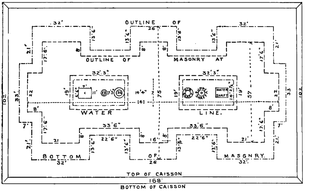
The caisson-foundations, built by Webb & Bell Construction and weighing 7000 tons each, are 102 feet by about 170 feet surmounted by a 15-foot-thick grillage (Brooklyn) or a 22-foot-thick grillage (New York), comprised of nine courses of 12- by 12-inch yellow-pine timber (48 pounds per cubic foot); all are encased in several-feet-thick, well-compacted Rosendale-cement concrete.
These components support the solid masonry tower-base pedestals, measuring about 59 feet by 140 feet by 20 feet high (Brooklyn), and 47 feet high (New York), measured from the water line to the top of the timber grillages. The pressure at the bottom of the foundation is 5½ tons per square foot (t/sf) (Brooklyn) and 6¾ t/sf (New York). Masonry base (pedestal) pressure on the timber grillage is 9¼ t/sf (Brooklyn) and 10½ t/sf (New York). This pressure is increased 8 percent by the superstructure weight. Concrete is 1: 2: 3 (cement-sand-gravel) (Brooklyn) and 1: 2: 4 for New York.
Towers and Stone Details
Above the deck rise the buttressed double-arches. The buttresses are additive elements to the three-shafts-with-pointed-arch tower structure. The towers ascend to a reentrant spandrel, water table, and entablature under the summits of 316 feet (Brooklyn) and 350 feet (New York). The New York tower is slightly larger than the Brooklyn tower.
The towers above the floor are rock-face, random-ashlar granite [153 pounds per cubic foot (pcf)], whereas below the water line they are limestone (calcium carbonate) protected from rainwater dissolving the carbonates. Granite is a textured, granular, igneous, and anisotropic rock. Roebling carefully specified a natural rock face surface on fine-granite set off by a 1½-inch chisel or ax-crafted draft-cut perimeters, a light color and no flaws. Thousands of loads were shipped by sea from the quarries after being split by drill holes and wedges, and the corners, ends, and rough-axed beds well squared by pitching chisels. Rosendale cement was applied in all of the ½-inch flush mortar joints. The Roebling office provided templates for each stone. The best quarry and stone-cutting workers were required for the precise squared bed and sides handwork; emerging early machine technology for hammer and chisel tooling was not high quality until c. 1900.
The towers at the arch faces, arch intrados, and spandrels are smooth peen-hammered or pecked to contrast with the rusticated surfaces of the adjacent buttresses. The arch surround on each transverse face displays a complex and striking saw-tooth stonework design, set in relief. The pointed arches have a radius of about 46 feet measured from the springing plane, with the extrados and intrados non-concentric. The towers are slightly battered from the water line to the tower top. Tower tops of 53 x 106 feet are 271 feet above mean high water and 159 feet high above the roadway. The keystones, of about 11 tons weight each, are also smooth pointed with three-inch drafts cut to a depth of three inches. The tops of the pointed arches are 117 feet above the roadway.
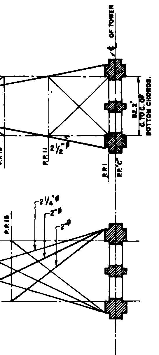
Collingwood Transverse Plan Section 1877.
The towers have a factor of safety of 2½; the cable’s safety factor is 6. Current live loads include at least 120,000 vehicles, 4000 pedestrians, and 3000 bicycles per day. Towers weigh about 79,000 tons (Brooklyn) and 97,000 tons (New York) with wall thicknesses ranging from 17 feet thick at the grillage to 10½ feet thick at high water.
Engineering Theory and Design Assumptions
Theoretical engineering analysis was far from understood in the 19th century. Engineers at the time continued to strongly favor testing by loading, rather than by the emerging elastic limit calculations which were considered by most, if not all, contemporary engineers to be unreliable “complications.” Graduating from Berlin’s Royal Polytechnic School in 1826, John Roebling benefited from the advanced German engineering schools, first established in the early 19th century. While engineering work was largely empirical, he likely studied with or under many of the leading contributors to the pool of knowledge on strength of materials and very early theory of structures, while also knowing of progress made in France’s Ecole Polytechnique, which would have included Louis Marie Henri Navier’s (b.1785) and others’ calculations on the thrust of arches. Arch theory was understood via geometric solutions since c.1700. In Roebling’s era, engineers and mathematicians proved graphically that the pressure line and the resistance line are two different curves. With this background, John Roebling devised several interesting structural innovations:
Cable Cradling for Arch Equilibrium
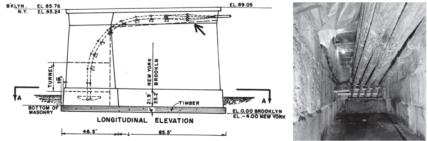
To attain equilibrium, compressive loads such as statically indeterminate arches must contain the line of thrust within the masonry section. However, the Brooklyn Bridge tower’s arch line of thrust would be 2½ feet outside of the outer shafts except that, as Washington Roebling commented in 1877 of his father’s design: “The main outer cables, when drawn in laterally, modify its position to such an extent as to throw its position six inches inside of that point, a condition of the utmost stability.” John Roebling had conceived of a mechanism to “cradle” the main cables. Additionally, in the days of empirical design, Roebling assumed that cradling the four main 15¾-inch-diameter cables, along with the over-floor and under-floor trusses and the tremendous weight of the cables (3600 tons, 53% of superstructure dead weight), would help to resist lateral forces.
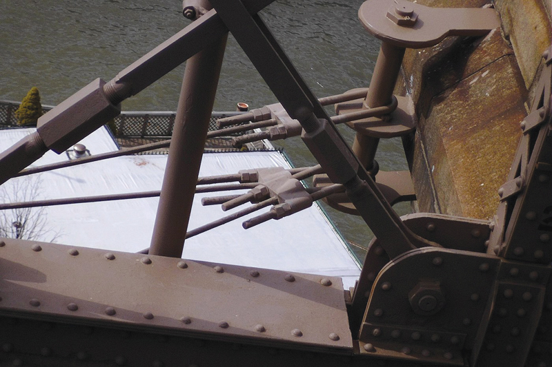
Cradling: Ammann DWG (left); Author’s photo today as built (right).
Lateral Force Resistance Mechanism
Iron bars are embedded flat across each tower’s transverse face near the top of the tower to reinforce tower resistance to various forces. Also, just below the floor at 119 feet above mean high water, Roebling inserted 2- by 10-inch steel or heavy iron bars longitudinally into and through the tower masonry, terminating in eye-bars exterior to each tower near the corner where adjustments to wires in plane with the main and land-span’s underdeck lateral-resistance truss are made.
Cable Ends to Anchorage Attachments
The massive anchorages weigh 60,000 tons each and rest on sandy strata which, after construction, settled into a stable state. The limestone blocks, with a bearing capacity of about 625 t/sf, are trimmed in white granite at corner quoins, arch voussoirs, and cornices. John Roebling specified high-quality limestone with a bold rock-face surface and a maximum 3-inch projection, the same as for the towers above the deck.
Etching of anchorage under construction.
The anchorages, which rise over a four-foot-deep timber grillage, were bolted and grouted for a tight seal, then filled with the same Rosendale cement-concrete as the towers. From both anchorage bases of about 129 x 119 feet, there is a straight batter of ½-inch per foot rise over about 85 feet elevation to 114 x 117 feet at the top.
Ammann DWG-anchorage mechanism, chains, anchor plate (left); HAER 1982 pix as built (right).
John Roebling used his 1846 patent for Rows of Anchoring Suspension Chains to Cables, invented for the Cincinnati Bridge over the Ohio River and enlarged for the Brooklyn Bridge. On the interior floor, four cast iron anchor plates, at 23 tons each and well weighted down by 650 cubic yards of granite stone, secure chains of parallel rows of pin-connected wrought iron anchor bars. The bars rise in a curved quadrant to attach to the cable ends at about eight feet under the deck level. Wrought iron was selected, after testing of that era’s early steel exhibited no physical advantages over that of iron.
Construction
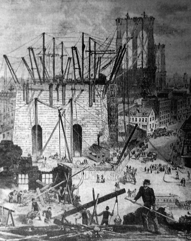
Rail tracks conveyed bridge components to sites from the waterfront. To build the arches, stone beds for the saddles, and tower tops, steam-powered hoists raised granite stones weighing nine tons or more, each, by way of lewising each stone. Each stone would have 4½-inch-deep mortises drilled into it, into which the counterpart tenon in the lewis device would fit, to grip the stone for lifting. Three hundred and fifty feet of 1½-inch steel hoisting ropes, powered by steam (sometimes dangerously oscillating from engine cycles), raised the stones for derricks to place into position. The stones of the anchorages, weighing up to six tons each, were hoisted and set by balance derricks; over that weight, derricks were tied to lewis holes and gaps in the completed stonework. The cast iron saddles and saddle plates by themselves weighed 182 tons.
Arch Blocks
Arcades of arched construction, with exterior faces of rusticated stonework trimmed with voussoirs of contrasting stone, run longitudinally under the floor of the long approaches landside of both anchorages. Here, John Roebling devised income-producing interior spaces intended for housing, shops, or offices within the arch blocks. Today, mostly vacant, all are under rehabilitation, managed by a collaboration of state and federal agencies, after vault cracking discovered in 2010 affected installation of a remote monitoring system. Fiber-optic sensors tracked structural movement, vibrations, and thermal data, after which a safety program was initiated.
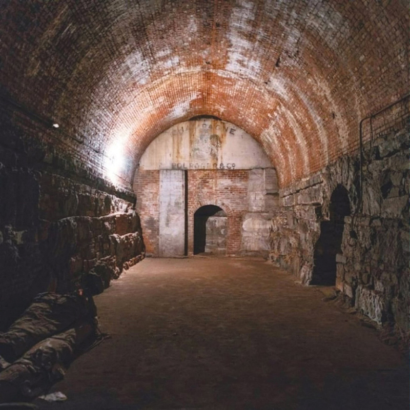
Arch block interior with vault transverse and longitudinal symmetrical and asymmetrical through-cracks, revealing various forces acting on the load bearing structure.
Ongoing Condition and Rehabilitation
The original approach-decking used in the superstructure – the nation’s second use of rolled structural steel sections in a bridge superstructure, according to HAER (Historic American Engineering Record) – was recently replaced with pre-cast, concrete-filled steel grid panels. Some approach under-deck arch block exterior walls are undergoing reinforced concrete infill rehabilitation.
Parts of the east-facing wall-element of the original unreinforced load-bearing limestone Brooklyn anchorage, which contained continuous vertical through-cracks, are also being infilled with reinforced concrete to improve structural strength. Similar cracks exist in the south wall of the longitudinal stairwell from the over-floor pedestrian walk to the street below. The use of modern materials and methods to replace original construction in flagship historic structures requires careful scrutiny and consideration of preservation principles. Another modern action is the application of sealant, which is sprayed periodically on the piers and tower parapets.
Considering that the Roeblings, with their wire manufacturing business, likely intended to celebrate – or at least emphasize – the inherent engineered applicability of the wire elements over the masonry itself, the combination of the tower’s basic, hardy, base-shaft-capital scheme, juxtaposed with the network of delicate-appearing structurally-interlaced wire, produced the powerful, continuing presence of the Brooklyn Bridge today.■
References
Ammann, Othmar and Holton Robinson. Brooklyn Bridge Technical Survey, Final Report. New York: Department of Public Works. http://hdl.handle.net/2027/wu.89078557691
Baker, I. O. A Treatise on Masonry Construction. 9th ed. New York: John Wiley & Sons. 1907.
Collingwood, Francis. “Discussion at the Seventh Annual Convention on Upright Arched Bridges.” Transactions of ASCE, CXIII: 1875, p. 205.
Collingwood, Francis. “Notes on the Masonry of the East River Bridge.” Transactions of ASCE, Vol. 6: CXXXIII, 1878, pp. 7-27. [Paper presented November 1, 1876.]
Green, S. W. A Complete History of the New York and Brooklyn Bridge: from its Conception in 1866 to its Completion in 1883. New York: S.W. Green’s Son. 1883. http://hdl.handle.net/2027/nnc2.ark:/13960/t9670rh9q
HAER (Historic American Engineering Reports). 1982 photos of Brooklyn Bridge with captions and report, NY-18.
HAER (Historic American Engineering Reports). Text Report: HAER-NY, 31-NEYO-90; No. NY-18.
Hildenbrand, William. Cable Making for Suspension Bridges. New York: Van Nostrand. 1877.
McKee, Harley. Introduction to Early American Masonry. Washington, D. C.: National Trust for Historic Preservation. 1977.
Roebling, John A. Patent Drawing, 1846, Roebling Papers, RPI.
Roebling, W. A. Pneumatic Tower Foundations of New York and Brooklyn Bridge. New York: Averell & Peckett. 1873.
Roebling, W. A. Report of the Chief Engineer of the New York and Brooklyn Bridge. Vol. 6. Brooklyn: Eagle Print, 1877.
Roebling, W. A. Washington Roebling’s Father; a Memoir of John A. Roebling. Donald Sayenga, ed. Virginia, USA: ASCE Publishing. 2009.
Sharif, M. Protecting New York City’s Bridge Assets. White Paper, NYCDOT. www.fhwa.dot.gov/preservation, 2013.
Petrosky, Henry. Engineers of Dreams. New York: Knopf. 1995.
Siegesmund, S. and A. Török. “Building Stone.” Stone in Architecture, by S. Siegesmund and R. Snethlage (eds.), Berlin: Heidelberg. DOI: 10.1007/978-3-642-45155-3_2.
Talebinejad, Iman, Fischer, et.al. “Hybrid Safety Assessment in Double Span Masonry Vaults in the Brooklyn Bridge.” J. Civil Structural Health Monitoring. Jun.., 2011.
Timoshenko, Stephen P. History of Strength of Materials. New York: McGraw-Hill. 1953.
Zink, Clifford W. The Roebling Legacy. N. J.: Princeton Landmark Publications. 2011.
Photo of Approach Arch Block Interior. https://www.untappedcities.com 5.24.2018; unknown photographer. Accessed 9.4.2018.