
Have you ever heard the phrase, “don’t judge a book by its cover”? The same quote can apply to the Town Center Parkway Rail Support Structure in Reston, Virginia. At first look, the hidden structure appears to be a reinforced barrier along a track. However, just like an iceberg, the true intricacies lie beneath.
Dulles Corridor Metrorail Project – Phase 2
Capital Rail Constructors, a Joint-Venture between Clark Construction Group, LLC and Kiewit Infrastructure South, won the Phase 2 Dulles Corridor Metrorail Project in May of 2013. Parsons serves as Lead Engineer for the Joint Venture. Phase 2 of the project consists of the remaining six stations, 11.4 miles of track and systems to connect Dulles International Airport to Washington D.C.
Like so many other projects before, there were many keys to the success of this project: addressing the diverse needs of multiple stakeholders, developing a design approach that provided a robust but economical structure necessary for both current and future needs, and, finally, incorporating the construction of the structure into the total project without a significant delay to the overall schedule.
Origin of the Town Center Parkway Rail Support Structure
The Town Center Parkway Rail Support Structure was added into Phase 2 of the Dulles Corridor Metrorail Project after contract award. At this location, the proposed Metrorail alignment runs within the median of the International Airport Access Highway (DIAAH). In early 2012, a study, led by the Fairfax County Department of Transportation (FCDOT) in collaboration with MWAA, WMATA, and VDOT, assessed the feasibility of extending the Town Center Parkway south to Sunrise Valley Drive, passing either under or over the Dulles Toll Road (DTR), DIAAH, and the future Dulles Metrorail corridors.
The origin of the Town Center Parkway extension project began after the planning and preliminary design of the Metrorail Project. The anticipated start of construction of the Town Center Parkway extension is not until sometime after the completion of the Metrorail Project. FCDOT, with the help of Parsons-Brinckerhoff (now a part of WSP), determined that a traditional overpass structure was not feasible. Constructing an underpass beneath an active Metrorail line would be difficult to permit after the Metrorail line was operational. In 2013, a resolution was approved between the MWAA, WMATA, VDOT, and FCDOT that a structure carrying the rail lines would need to be built during Phase 2 Metrorail Project work. The proposed schedule was to eliminate or at least minimize the disruption of the rail service in the future construction of the Town Center Parkway extension.
To move this feasibility study forward without impacting Phase 2, FCDOT developed preliminary engineering plans for the structure, then MWAA and WMATA developed a cost for final design and construction with the help of Capital Rail Constructors. Once all parties reviewed the cost estimate, Fairfax County determined the change order to incorporate the rail structure was a betterment to the area and recommended this project be incorporated into Phase 2. The successful early collaboration between all stakeholders was necessary to include this new project into the Metrorail Project schedule.
Final Design and Analysis
The new structure presented unique challenges including stipulations from each stakeholder for the project to move forward. Stipulations included minimizing long-term maintenance costs, a maintenance-free interim phase (prior to excavation for the Town Center Parkway), and flexibility for the future road alignment. This led to the development of an unconventional solution, a structure that later would be unearthed to become a bridge, with an excavation depth not yet decisively defined. The structure will begin its life as a slab on grade supported by three secant pile walls (“interim condition”) but will become a two-span rigid frame bridge when the Town Center Parkway extension is constructed at an undefined time in the future (“final condition”).
The test for the design team was to detail a structure based on a concept for a road whose layout would not be finalized until after the structure was completed while meeting the durability and resilience requirements in the interim and final phases. The complexity of the design was in providing a flexible solution that would not restrict the future Town Center Parkway Extension alignment.
The strategy was to define an envelope for the future road that all stakeholders would approve, then analyze and design the structure around the envelope. The two-stage process in determining the envelope was first to outline the physical restraints involving the minimum and maximum excavation depths and roadway widths. The second was to define a series of excavation approaches within which the future construction team could work.
By embracing design techniques and innovative thinking more commonly seen in tunnel construction, the design and construction teams were able to deliver a structure that met all stakeholder requirements and provided flexibility for the future excavation of the structure.
Structural Modeling and Design Loading
Capturing the geometry and construction impacts required the use of complex modeling techniques and post-processing solutions. The approach utilized Soil Structure Interaction (SSI) Modeling to determine the soil responses and 3-Dimensional Finite Element Modeling (3-D FEM) to evaluate the concurrent loading created from the SSI models with loads such as track loading and other transient loading.
Because future excavation will be performed within and below the structure, the actual ground forces and construction sequences on the structure drive the system’s structural behavior (stiffness). For this structure, the SSI design approach was the appropriate analysis rather than a traditional pre-determined force (strength limit) equilibrium design approach. The SSI approach captured the stiffness of both structure and soils, as well as the interaction between the surrounding soil excavation. The SSI model simulated the non-linear, elastoplastic soil deformation behavior to provide an accurate structure deformation prediction.
Multiple excavation sequences were considered to determine the worst case scenario force effects acting on the framed structure. This information was used to capture how the future contractor may perform the unearthing of the structure. Examples of these variables are initial construction activities including “over-excavation” to lay down a subbase for the future Town Center Parkway and whether the future contractor would unearth the structure one span at a time or in parallel. These different boundary conditions, including the long-term soil effects, were combined to determine the controlling concurrent loading at critical locations within the structure.
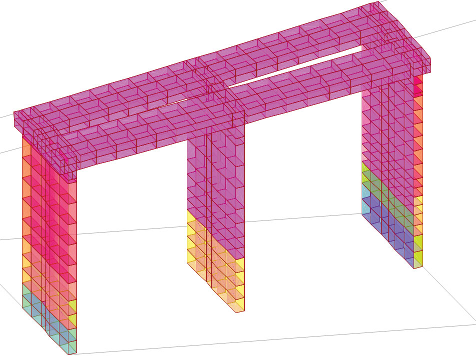
Figure 1. Example 3-D FEM model.
The results of the SSI models provided soil pressures and structure deformations necessary to derive non-linear soil springs for the 3-D FEM. The future at-rest pressures were also evaluated by combining a semi-SSI approach with the SSI derived non-linear soil springs. The derived structural deflections and soil loading from the SSI models created the basis for the structural models.
The secant pile walls and deck slab elements were then analyzed using 3-D FEM. The walls and track slabs were detailed as rigid frames to minimize soil deflections in the walls and track deflections in the slabs in the future conditions. Significant moments and torsional loads at the interface between the walls and track slabs had to be considered due to the skews of the walls. The surface loads, including the at-rest soil pressure, pore pressure acting on the faces of the walls, and the deck slab loads from the ballast and tracks were applied as area loads along the surfaces of the solid members in the 3-D FEM. The Project Directed Rail live loads were modeled as moving loads along alignments to capture the influence of the Inbound and Outbound track loads. Examples of other loads within the 3-D FEM included train derailment force modeled as a modified vehicle, temperature loads, wind loads, rolling forces, seismic forces, concrete creep and shrinkage, longitudinal train braking forces, and a future vehicle collision force against the center wall from an impact along the future Town Center Parkway. The output from the 3-D FEM models was combined through post-processing techniques developed by Parsons, and the capacity of the structure was determined using AREMA Reinforced Concrete Specifications. Figure 1 shows an example 3-D FEM model of the structure with soil loads applied based on one of the excavation conditions.
Construction Planning and Implementation
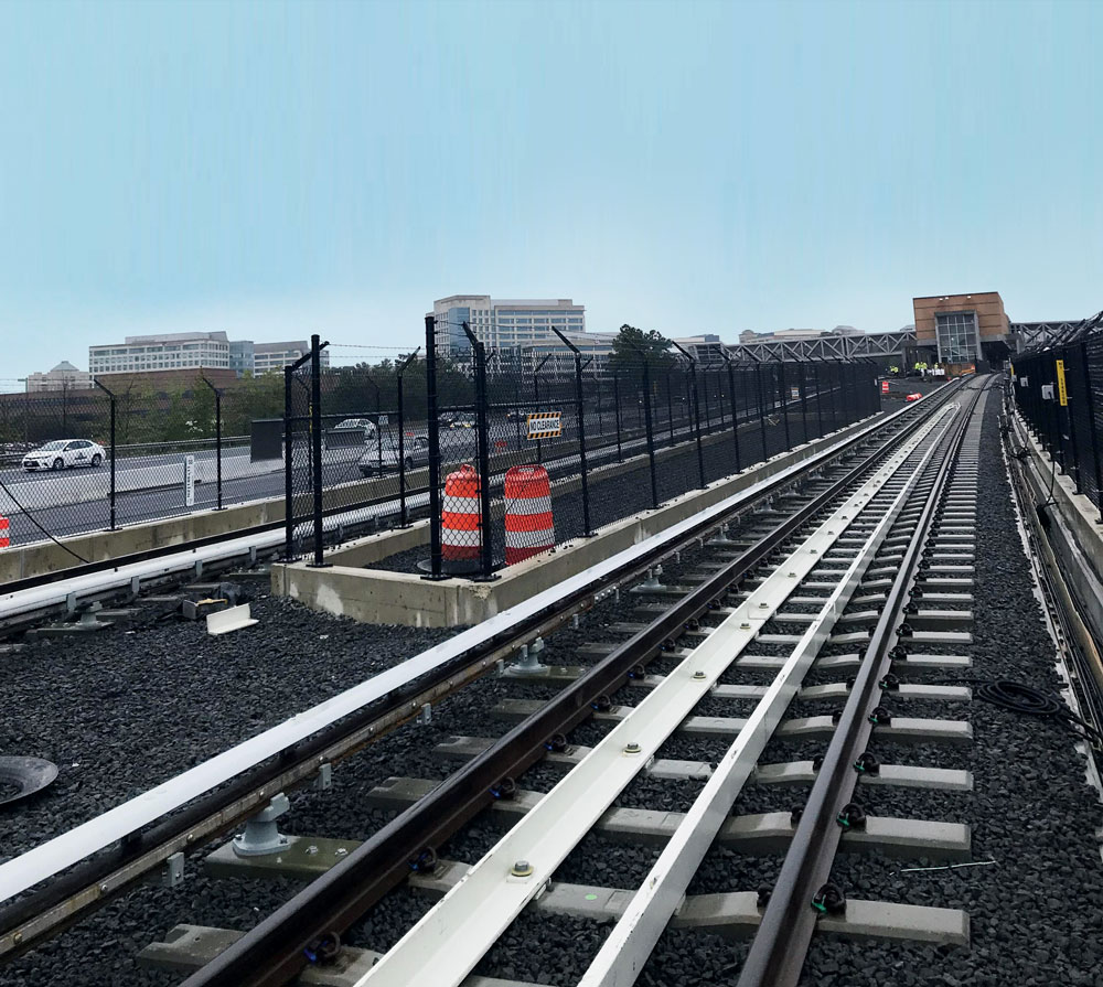
Figure 2. Completed structure in the interim phase.
Construction planning of this project started early in the design process. How the structure was built now would dictate to a large degree how the future excavation for the Town Center Parkway extension would be accomplished. The structure was constructed by first excavating to the bottom slab depth; then the secant pile walls were installed. Once the walls were finished, the slab and barriers were completed and the ballast placed, covering up the entire structure except for the barriers. Figure 2 is a photo of the completed structure in the interim condition. Figure 3a shows an elevation view of the structure in the interim condition and Figure 3b an elevation view of the structure in final condition.
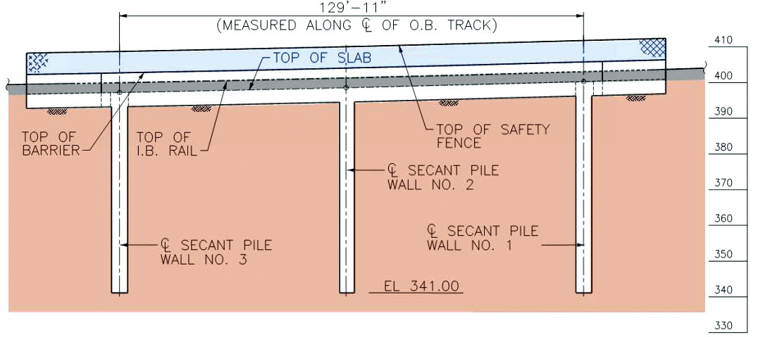
Figure 3a. Elevation view of the structure in the interim condition.
The walls required heavy reinforcement to provide excavation flexibility. The design and construction teams worked closely throughout the final design and construction phases to develop a construction procedure including a reinforcement arrangement that would maintain the necessary spacing to ensure proper concrete placement. This included innovative construction techniques, such as the Contractor’s use of a custom in-field reinforcement bending machine capable of bending bundled #14 secant pile rebars that provided the necessary development for the moment connection between the secant pile walls and the track slab (Figure 4).
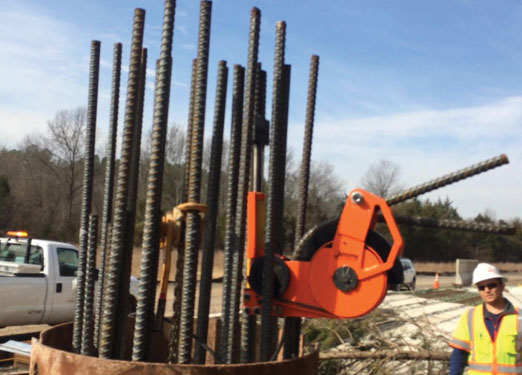
Figure 4. Field bending of bundled #14 reinforcement.
Conclusion
The Town Center Parkway Rail Support Structure presented many challenges that required unconventional solutions. The ability to incorporate changes in the design-build delivery method allowed for increased coordination between team members and paved the way for successful construction. By utilizing state-of-the-art soil interaction and structural engineering analysis tools, techniques, innovative construction procedures, and open collaboration between all parties including Fairfax County, WMATA, MWAA, and Capital Rail Contractors, a design was envisioned and implemented that could meet the needs for the local community for years to come.■