
Evaluation and Repair of Fire Damaged
The use of Metal Plate Connected (MPC) wood roof trusses is a common structural framing system used in residential and light commercial structures. Low initial cost of fabrication, ease of installation, and ability to accommodate varying profiles are some of the advantages of this type of roof framing system. However, when these trusses are damaged by fire, evaluation and repair of the trusses can be challenging. This article presents methods for evaluation and repair of fire-damaged MPC wood roof trusses and discusses the factors that go into the decision whether to remove and replace or repair-in-place, as illustrated by several real-life case studies.
Design Repair Phase
It is important to keep the client’s overall cost and schedule in mind, as they may take precedence over a sophisticated repair design that minimizes the number of repair materials used. The remediation contractor usually likes simple repetitive details and more repetition, which typically lowers the unit costs.
Primary considerations in the repair versus replacement decision include:
- From a global perspective, if a high percentage of the trusses are damaged, and only a few trusses can be salvaged, it is better just to replace all the trusses. Matching up the alignment of new and pre-existing trusses that may have deflected or sagged over time can be problematic and difficult. Where possible, group replacement trusses by configuration, slope, function, or location. Extend the truss replacement area to an expansion joint or a convenient architectural breakpoint such as a roof valley or ridge.
- Within a truss, determine if there are enough undamaged members that can remain in place to allow the repair of the damaged members. Generally, if more than 25% of the members in a truss need repair, then it might be better to replace the entire truss.
- The repair versus replace decision must also take into account non-structural factors such as mechanical and electrical utilities that run through the trusses. Total removal and replacement of damaged trusses may be more costly because of the need also to remove and replace/reinstall the utility lines. This idea also applies to expensive roof coverings and ceiling finishes. More extensive in-place repairs and temporary shoring of the damaged trusses may be justified by these other costs.
- Consider how the remediation contractor will access tight working spaces, such as attics, for both workers and materials. Temporary openings can be cut in end walls or holes cut in ceilings and the roof to bring in materials. If new replacement trusses are needed, a small crane will be required to place the trusses. Access to set the crane within a reasonable reach of the delivery truck and the placement location can be a critical factor.
- Consider the costs of cleaning smoke residue and sealing odors on the trusses that will remain in place. Soda blasting, dry ice, and sanding are typical cleaning methods with a final application of a sealant used to provide odor protection.
Many times the answers to the above items are easy to make, and the repair versus replacement decision is an obvious one. However, for more complex situations, the decision-making process can be complicated because it involves issues beyond structural calculations.
Concerning the actual repair of the MPC trusses, there is often a tendency to go with full truss replacement because it is felt that the repair of the trusses is inherently a costly item and requires an extensive amount of technical expertise. Some contractors claim that local building officials mandate that the only person that can modify an MPC truss is the original designer of the truss. This is not accurate. As professional engineers, we can modify existing structural elements provided we have the required technical expertise, and we take responsibility for the entire truss that we are repairing.
Truss Repair Techniques
A structural analysis of the truss must be performed to understand the distribution of the forces, moments, and stresses. Generally, it is sufficient to assume all members are pinned and that secondary moments are neglected if panel point spacings are reasonable. Generally, conservative sizing of repair members and connections is not a significant cost driver because the majority of the repair cost and schedule may be associated with accessing the repair area and getting materials to the repair location. An additional 15% to 20% increase in the repair design factor of safety is reasonable, given the unknowns in the conditions of the members that remain, the difficult conditions that the contractor has to work in, and construction tolerance and fit-up issues.
The most common and most straightforward repair is to use sisters to existing members that have sustained minimal damage. This usually involves localized charring of a member that is not located near a panel point or a joint. The sisters will generally be the same size as the main member, with sisters on both sides to maintain symmetry. If access to only one side of the damaged member is possible, the eccentricity of a one-sided connection is generally not a problem for members with low forces. Be sure there is enough good remaining material to fasten the sisters to and provide a long enough lap splice length beyond the damaged area to develop the forces required. The cost difference between using a 6-foot long or an 8-foot long 2×4 is negligible, so it is important to ensure you have the appropriate length of the sisters.
Many designers use 10d or 12d nails in single shear because framers typically have nail guns that use these nails. If spacing limitations are present, Simpson metal straps, steel side plates, or through-bolts can be used. Through-bolts in double shear have higher allowable shear forces that can be up to 10 times greater than nails.
The second most common repair is the replacement of a damaged member between two-panel points utilizing plywood or OSB gusset plates for connection at the panel points. It is preferred to use gusset plates on both sides of the truss to keep the forces symmetrical. The connection forces to size the gusset plate fasteners will be determined from the structural truss analysis. Once again, 10d or 12d nails in single shear are used through the gusset plate on each side of the truss. As an alternative detail, one can use 14d or 16d nails in double shear by driving the nail completely through both gusset plates and clinching the end of the nail on the back side. This will result in fewer nail holes in the truss members. However, for both methods, holes should be pre-drilled in the members if splitting becomes a problem. The spacing of the nails at 3 to 4 inches is usually preferred to help avoid splitting of wood.
The size of the gusset plates will generally be large enough such that shear or tension stresses in the gusset plates are not a problem. The size of the gusset plates will also be much larger than the existing MPCs. MPCs are a proprietary product with high allowable stresses based on extensive testing. The factor of safety used for the design of the plates is also reduced compared to the typical factors of safety applied to wood members connected with nails or bolts. Therefore, do not be surprised at the large number of nails required and the larger size of the gusset plates for members with high loads.
The final type of repair to be discussed is a full depth gusset plate. Rather than trying to repair individual panel point connections and members, plywood or OSB side plates are installed from the top chord to the bottom chord creating a box beam. This situation can occur for trusses with minimal depth where member forces are high, and there is not enough room to develop the full force of the member in the room allotted for the gusset plate. This can also occur where the truss members are installed flatwise. The internal web members could be replaced, but there will not be enough room for the required number of nails to develop the full force of the web members. Therefore, the web members are omitted, and the beam is designed with the side plates carrying the entire shear forces and the top and bottom chords forming a tension-compression couple to carry the bending moment. The connection between the side plates and the chords is designed using classical shear flow theory which generally results in a reasonable nailing pattern.
Normally, the side plates are extended one to two panel points beyond the damaged/repaired area to provide a “transition zone” between the original truss section with discrete web members/forces and the box beam section with shear stresses in the side plates. Normally, a two-panel point transition zone is used near the ends of a truss where the shear stresses are high. Near the middle of a truss, a one-panel point transition zone beyond both ends of the damaged/repair area is needed. If there are concerns about high member forces in the webs and the transition of these forces to shearing stresses in the side plates, a finite element analysis can be performed to evaluate this. In general, when this type of analysis is performed, the transition zone from discrete web and chord member forces to distributed shearing stresses in the side plates occurs within the first half of the first adjacent panel point because the stiffness of the side plates is greater than the discrete web members. Another method of confirming the adequacy of the repair is to load test the truss.
Case Studies
Sister Repair Detail
There was minimal damage to the bottom chord of three trusses due to a fire from below. The Howe trusses spanned 40 feet and were composed of 2×4 members. There were numerous ducts, water pipes, and electrical conduits that ran through the openings in the trusses. There was sprayed-on foam insulation on the underside of the roof sheathing that was not damaged.
Because the damage to the three bottom chords only included minor charring of the 2×4 bottom chord member at two locations and the near-by metal plate connectors were not damaged, isolated repair of the damaged chord members was selected (Figure 1). This eliminated the need for the full replacement of the trusses, finishes, insulation, and utility lines.
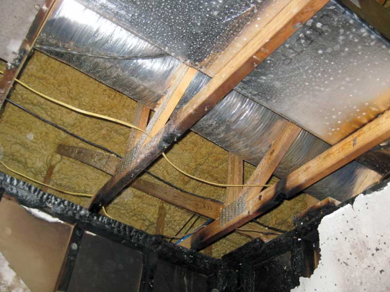
Figure 1. Charred bottom chord truss members.
The force in the damaged bottom chord was 3,240 pounds tension. It was conservatively decided to sister the bottom chord with an eight-foot-long 2×4 on both sides to provide an additional allowance for fit-up. Because of the relatively high member force, the use of 5⁄8-inch diameter through-bolts was selected for the fasteners. Three bolts at each end of the sisters were sufficient, but a fourth bolt was added near the panel point to provide additional capacity and stability (Figure 2).
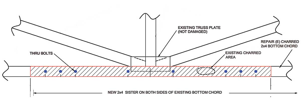
Figure 2. Repair detail for bolted sister members.
Nailed and Bolted Gusset Plates
Portions of the top chord, bottom chord, and a web member were partially consumed by a fire from below (Figure 3). The metal plate connectors at the ends of the damaged members were warped from the heat of the fire. The Howe trusses spanned 45 feet and were composed of 2×4 web and bottom chord members with 2×6 top chord members. The damaged trusses sandwiched a plenum above an HVAC unit below. Large horizontal ducts came out of the plenum and were routed between the web members of the truss. The underside of the roof sheathing above was covered with smoke residue but was not structurally damaged. Isolated replacement of the damaged truss members was deemed to be more cost-effective than total removal and replacement.
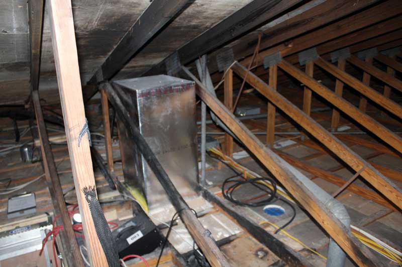
Figure 3. Damaged truss members and the HVAC plenum.
The force in the damaged top and bottom chord members was 4,500 pounds. The maximum force in the damaged web members was 1,300 pounds. Plywood/OSB gusset plates were used to connect the new members at the panel points. Because of the relatively high member forces in the top and bottom chords and interferences with the ducts, 5⁄8-inch diameter through-bolts were used to minimize the size of the gusset plates (Figure 4).
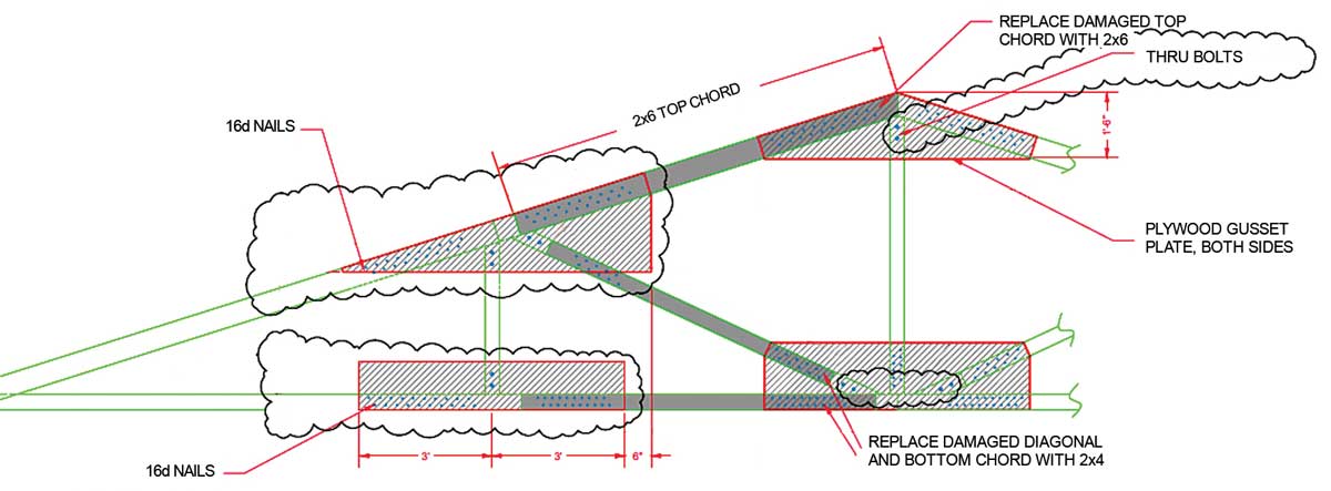
Figure 4. Repair detail using bolts for select connections.
Box Beam Design Repair
Portions of the top chord, bottom chord, and web members at the ends of four 60-foot-long hybrid Warren trusses were partially consumed by fire (Figure 5). The trusses were a parallel wood chord truss 4 feet deep with 1-inch diameter hollow steel pipes for the web members. The top and bottom chords were 2×4 stress rated wood members laid flatwise. The web members were connected to the top and bottom chords with a single ½-inch diameter through-bolt at each panel point. Approximately 8 linear feet of the four subject trusses were damaged at one end. Total replacement of the trusses would have required removing and replacing numerous ducts, pipes, and electrical conduits that were threaded through the trusses. Also, there was a long lead time to fabricate the trusses, and a small crane would have been required to set the new trusses. Even though the construction of the trusses was unique and the member forces were very high, it was decided to temporarily shore the trusses and perform isolated repairs.
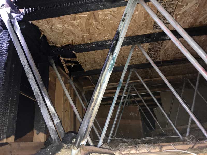
Figure 5. Damaged top chords of the hybrid truss.
The vertical reaction at the ends of the trusses was 2,100 pounds. The force in the first diagonal web member was 2,200 pounds. Trying to pass this force through nailed gusset plates was not workable. Using through-bolts in the flatwise chords similar to the existing connections was also not workable. Hence, it was decided to make a box beam at the end of the truss using full height plywood/OSB side plates. The box beam concept extended the 8-foot damaged length of the truss and then another 8 feet to create a two-panel point transition zone (Figure 6). A finite element model was run to investigate the stresses. Because the plywood/OSB side plates are stiffer than the discrete web members and chords, there was a localized area of high shear stress in the side plates that only extended about 8 inches from the ends of side plates. This was deemed acceptable because minor slippage of the nails would redistribute the high localized shear stresses over a large area.
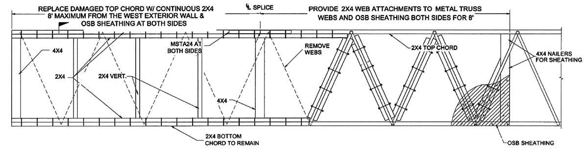
Figure 6. Repair detail at the end of the hybrid truss.
Conclusion
There are various methods for evaluation and repair of fire-damaged MPC wood roof trusses and many factors that go into the decision whether to remove and replace or repair-in-place. Consider the repair solutions presented as an alternative to the replacement of fire-damaged trusses.▪