
Means and Methods for Renovation of the Boston Public Library Johnson Building
The recent $78 million transformation of the Boston Public Library by William Rawn Associates of Boston, Massachusetts, opens up the Library’s Johnson Building to become a more inviting public space. It improves the connectivity between the Johnson Building, 1972, and the Library’s original McKim Building, 1895. The structural scope to accomplish the transformation included the removal of an existing floor to create a grand two-story lobby along Boylston Street and removal and replacement of a portion of a 7-story column for the installation of a new glass elevator. Also included was the support and removal of concrete walls and removing a segment of a heavily loaded masonry bearing wall to create a long-missing link between the Johnson and McKim Buildings. The renovation occurred while the building remained occupied and open to the public. The article Handle with Care published in STRUCTURE (September 2018), summarized the main challenges and structural solutions to accommodate the ambitious renovation.
The primary structure for the transformation, design by LeMessurier as the Engineer of Record, considered the “means and methods” of how the structure might be altered. Drawings presented proposed construction schemes including shoring, bracing, jacking, and sequencing. The contractor, Consigli Construction, was ultimately responsible for the temporary conditions during construction. Consigli Construction engaged Becker Structural Engineers to facilitate the details of the construction means and methods. Engineered shoring, erection, and jacking sequences required early collaboration and communication among the design and construction teams.
McKim wall removal construction sequencing.
McKim Wall Opening
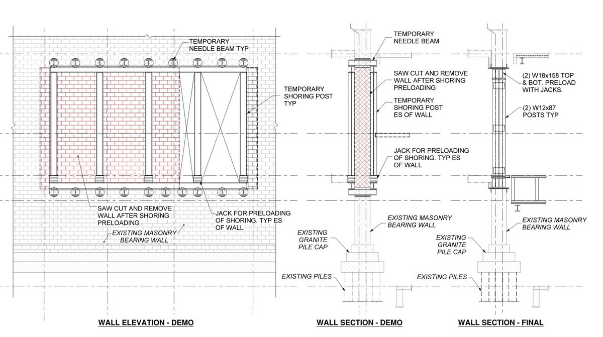
Connecting the Johnson Building to the original McKim building required a 36-foot opening in the McKim Building’s century-old brick masonry bearing wall. The existing wall consisted of a 30-inch-thick unreinforced masonry brick wall supporting a load of over one million pounds. The wall supported terracotta arch masonry floors spanning between iron beams. Foundations for the wall consisted of unreinforced granite walls and pile caps supported by timber piles, typical for the Boston Back Bay at the time.
Rigid steel framing consisting of double W18x158 beams above and below the opening, supported at the ends and approximate beam third-points with W12 columns, were used to support the wall above. The 3-span continuous beams were designed to limit live load deflection to 1⁄16 of an inch. Stiff framing was provided so as not compromise the masonry wall and brittle terracotta masonry floor arches, as well as to adequately distribute the load to the original granite foundation wall and timber piles below.
The structural drawings showed recommended sequencing along with conceptual shoring for the general scheme used in the design. The existing wall was cored above and below the opening to allow for W10 needle beams to be inserted and fully grouted into the wall. The temporary shoring consisted of W10 spreader beams engaging the needle beams, each side of the wall spanning between proprietary shoring posts. To insert the new W18 beams at the base of the wall, a portion of the wall needed to be removed which compromised the support of the existing first floor McKim beams. The W10 spreader beam provided temporary support for these beams until they could be reattached to the structure.
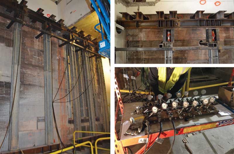
McKim wall removal temporary shoring. Temporary needle beams and shoring at McKim wall (left); Temporary needle beams, jacks, and jack boxes (upper right); 14 jacks used to simultaneously preload McKim Shoring (lower right).
Complete drawings for the existing McKim structure were not available. Exploratory work performed between concept and final shoring design resulted in changes, including coordination of needle beam and post locations to avoid existing framing above and below the opening. A lintel beam above an existing double door opening was discovered at an elevation higher than anticipated. The lintel conflicted with the temporary needle beams. Pre-shoring of the header within the existing opening was provided to support the wall and allow for coring of the lintel and installation of needle beams.
Both the final structural steel framing and temporary shoring were preloaded with jacks to limit deflections of the existing McKim Building unreinforced masonry walls and terracotta masonry floor arches. Fourteen independently controlled hydraulic jacks were used during preloading of the shoring. Custom jack boxes at the top of the posts were designed to accommodate hydraulic jacks to allow for preloading of the framing. The tops of shoring posts had to be temporarily braced to each other and to the wall to provide stability of columns during preloading of the wall.
Load requirements were coordinated between the design and construction teams. Loads were independently calculated, with dead loads of approximately 25.5 kip/ft and unreduced live loads of 6.5 kips/ft. It was agreed to preload the frame to 75% of calculated dead loads. Fourteen independently controlled hydraulic jacks were used during preloading of the shoring while nine inflatable air jacks were used to preload the final framing.
One of the most critical components of the construction sequence was monitoring during preloading. Representatives from LeMessurier, Becker, and Consigli were present for all jacking operations. Preloading occurred at night when floors above were closed to the public. Deflection monitoring points at the top, along the length of the opening, were set up to continuously monitor for movement. No measurable movement was observed during jacking operations, demolition, and after temporary shoring removal.
Johnson Wall Removal
Between the new Boylston Hall and the new opening to the McKim building was an existing stair servicing all floors. Two 10-inch-thick by 8-foot-long reinforced concrete walls on either side of the stair supported both the stair and surrounding floor structure. The walls not only supported vertical loads but also acted as cantilevers extending from the mat slab foundation. The transformation required the relocation of the stair and the removal of the walls to provide an open and clear connection between spaces. Temporary lateral wall bracing was provided between walls to allow for removal of the mezzanine slab prior to removal of the wall. Also, a 4-foot 2-inch opening was made in each of the walls above the second floor to accommodate the relocated stair.
A steel framing scheme was developed to allow for erection, jacking, and demolition without the need for temporary shoring. Cantilever steel framing was provided to support the wall above the second floor. Two W24x250 beams, one on either side of each wall, cantilever 10 feet with a 10-foot backspan and are both supported by a shared system of W36 girders and W14 columns. One column was required to be discontinuous and supported by a transfer girder at the first floor to accommodate the architectural program. The original 7-foot-thick reinforced concrete mat slab provided flexibility in locating new columns as required to meet the architectural layout without the need for new foundations. The wall sections to remain on either side of the new opening above the second floor were reinforced with concrete sections on either side of the wall, creating two reinforced concrete columns per wall. W12 needle beams centered below the newly created columns (i.e., two W12s per wall) were designed to transfer the load between the walls and steel framing. The framing was designed to limit live load deflections to L/800.
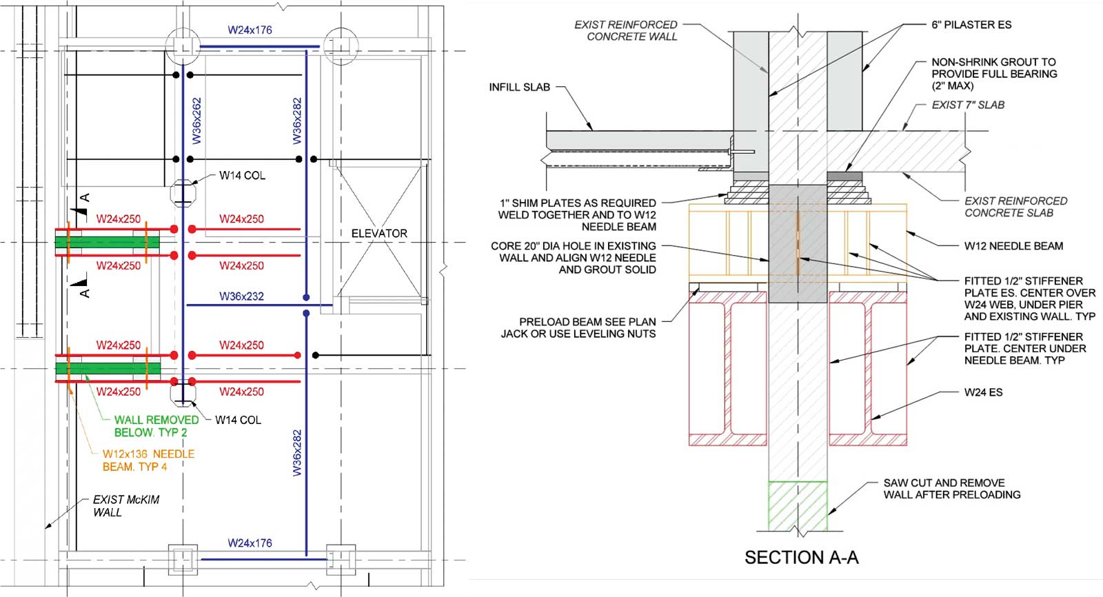
Johnson Building wall removal. Partial plan of second floor framing at Johnson wall removal and McKim Link. Green – removed walls below. Red – cantilever
and backspan W24. Blue – support framing. Orange – needle beams. McKim wall let; (left) Wall to W24 detail (right).
Walls were estimated to each support a load of over 450 kips, with unreduced live load representing approximately 15 to 20 percent of the total. The steel framing was preloaded for the estimated dead load with hydraulic flat jacks to limit deflection, reduce the required steel tonnage, and protect the existing Johnson Building. Jacks were located between each end of the needle beams and W24 cantilevers, a total of four jacks per wall. The initial Contractor-proposed scheme was to preload a pair of W24 beams at one wall, remove the jacks and then preload the second pair of W24 beams at the other wall. The design team demonstrated that over 25% of the force would be lost in the first W24 pair when the second pair was loaded. Therefore, it was agreed that both pairs of W24 beams would be loaded simultaneously to eliminate any preload losses.
Deflections were monitored during preloading to ensure that calculated wall weight was accurate and the building was not raised. Preloading resulted in approximately 1¼ inches of deflection in the steel framing with less than 1⁄8-inch of deflection in the framing after jack removal.
Johnson Column Replacement
One architectural feature of the renovated space included a new glass-enclosed elevator adjacent to and in front of the McKim opening that replaced a double elevator bank in the existing Johnson Building. The new elevator was located directly next to an existing concrete column that was braced by the existing mezzanine. The mezzanine was removed as part of the project to create Boylston Hall. The existing concrete column was replaced with a new, slender, built-up steel tube column, ten inches square with 1½-inch-thick walls to minimize the visual impacts of the column in proximity to the glass elevator. The column replacement occurred at about the third point of the total column height; two levels of sub-basement located below the main level and the column extended upward another 6 stories above where the column was replaced. The major challenge in replacing the column was how to shore the loads above the work area, remove the existing column and then install the new column.
The original construction concept was to shore around the column for the full height of the building. However, the spaces above the column were occupied and some of them recently renovated. Further, mechanical and electrical support spaces located in the sub-basement below the column limited the opportunities to shore. It quickly became clear that the vertical extent of shoring would need to be limited to reduce the impact on the other spaces outside the scope of the renovation.
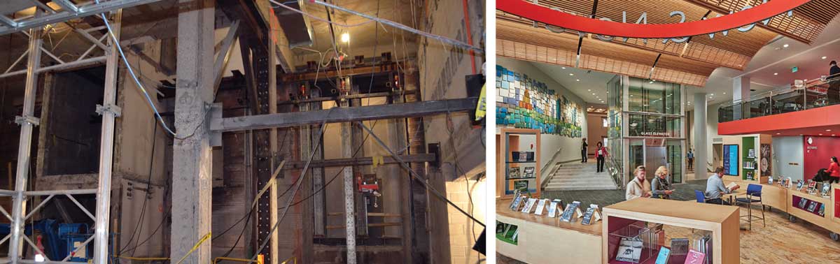
Temporary shoring for McKim wall removal, Johnson concrete walls remain for new link (left); Finished McKim Link (right). Courtesy of Bruce T. Martin.
The shoring scheme utilized to replace the existing column was to construct a steel collar around the existing column above the second floor. The collar was constructed of steel channels and plates, with adhesive anchors utilized to transfer the column loads to the collar. Just above the second floor, two steel girders were utilized as jacking points. Jacking of the column above was considered critical to assure that the load would be removed from the existing column and transmitted to the shoring system. The steel girders were supported on temporary W12 steel columns. The columns were grouted to the floors that were to remain, but cored through the existing mezzanine so that the mezzanine could be removed once the column was unloaded. Column locations were coordinated in extremely tight spaces, avoiding active electrical conduits and other utilities. In one location, a column flange had to be notched and the remaining column reinforced for the column to fit in the proper location. At another level, the temporary column forces had to be redirected with a transfer girder cantilevering at each end to avoid interferences. The bases of the columns were founded on the existing 7-foot-thick foundation mat.
The column load supporting the existing two-way concrete flat plate was estimated at 550 kips with full live load, which was included when sizing shoring elements. Only dead load was considered when determining jacking forces for shoring preloading. Because some of the floors supported by the column that was being shored were occupied during regular library operations, the jacking and cutting of the existing column were performed at night, during off hours. To ensure that loads were properly removed from the existing column and transferred to the shoring system, monitoring points were established on the jacking collar. The points were observed for movement during jacking using a construction auto level located away from the jacking site.
Two hydraulic rams, with a common manifold, were used to jack the collar from the steel girders. The common manifold was needed to ensure that the jacks on either side of the column were lifting at the same pressure and, therefore, a balanced force. The jacking was stepped at 25-kip intervals, with a 10-minute hold at 50-kip intervals to allow for monitoring of the structure and to observe any slippage that might occur in the column collar. The maximum predicted jacking force was 320 kips. At 275 kips, the collar had moved up 1⁄16 inch, indicating the column was raised. At that jacking increment, it was decided to lock off the hydraulic rams.
It should be noted that the original column load calculation included an allowance for the existing Concrete Masonry Unit (CMU) elevator shaft above the jacking site to be grouted solid. The in-place shaft was constructed with un-grouted CMU. The maximum predicted jacking force would be 292 kips, or within 6 percent of the actual jacking force after adjusting the calculations to remove the grout. Also, note that no live load was considered for jacking, even though the areas above the column contain spaces that would normally be designed for 100 psf or more. The decision to exclude live load was based on field observation which found many open spaces which were not occupied during the night operations and therefore had little contribution to the actual column load.
To install the new column, the demolition of the existing column required a clean cut where the column met the structure above and below. The initial cutting was performed at the level directly below the jacking site at the top of the column. A 42-inch-diameter hydraulic rotary cutting saw was utilized to make the cut immediately after jacking. After demolition, the new steel column was set, grouted in place, and anchored top and bottom with adhesive anchors completing the column replacement.
Summary
Contributing to the success of the transformation of the Boston Public Library Johnson Building was early consideration of the construction process by William Rawn and LeMessurier. Consideration of the “means and methods” within the design, and providing concept shoring and erection procedures, gave the Contractor and their subs confidence to bid and execute the ambitious structural renovation and ensure the Architect’s vision was realized. This level of detail and collaboration continued into the construction phase with well planned, open, and professional dialogue between the design and construction teams, with Becker Structural Engineers serving as Consigli’s means and methods engineer. In-house design charrettes, and design and pre-construction meetings, were integral in developing the final scheme and executing the work. Final temporary shoring, bracing, and preloading calculations and design were submitted, reviewed, and discussed with the design team, ensuring transparency in the design approach, expected outcome, and concerns. Shoring, bracing, jacking, demolition, and installation of the new steel framing went smoothly as a result of rigorous design, good planning, frequent field observations, and strong collaboration between the Architect, Engineer of Record, the Contractor’s means and methods Engineer, and the Contractor.▪