
Renovations at Wrigley Field
In 2014, Wrigley Field turned 100 years old. In 2016, the Chicago Cubs played their 100th year at the ballpark and won the World Series for the first time since 1908. The Ricketts family has been pursuing an extensive renovation of Wrigley Field, including the stadium and surrounding area, since purchasing the Chicago Cubs baseball team and Wrigley Field in 2009. Following months of negotiations between the team, Alderman Tom Tunney, and Chicago Mayor Rahm Emanuel, the project received endorsements from the Commission on Chicago Landmarks, the Chicago Plan Commission, and final approval by the Chicago City Council in July 2013.
The lineup of renovations called for a $575 million, privately funded rehabilitation of the stadium to be completed over the course of five years. The proposal included improvements to the stadium’s façade, infrastructure, restrooms, concourses, suites, press box, bullpens, and clubhouses, as well as the addition of restaurants, a patio area, batting tunnels, a 5,700-square-foot video board, and an adjacent hotel, plaza, and office-retail complex. The renovations are now expected to be completed in six phases during consecutive off-seasons, shortened by the end-of-season playoffs.
Thornton Tomasetti (TT) was recruited as the structural engineer of record for the ballpark renovations, plaza, and an office-retail complex. This article focuses on some of the structural and geotechnical challenges associated with evaluating the design and condition of the 100-year-old stadium and the structural engineering behind the improvements mentioned above.
Strengthening Foundations
The proposed improvements to the stadium required the transfer of additional loads through the columns to the foundations. Right off the bat, TT determined that the structural capacity of the existing typical “wedding cake”-style footings was not sufficient to support the new program and required strengthening. In addition to the higher loads, the new program also involved construction of a basement below the ground level on the field side of column line F and the plaza/office building on the street side of column line A (Figure 1).
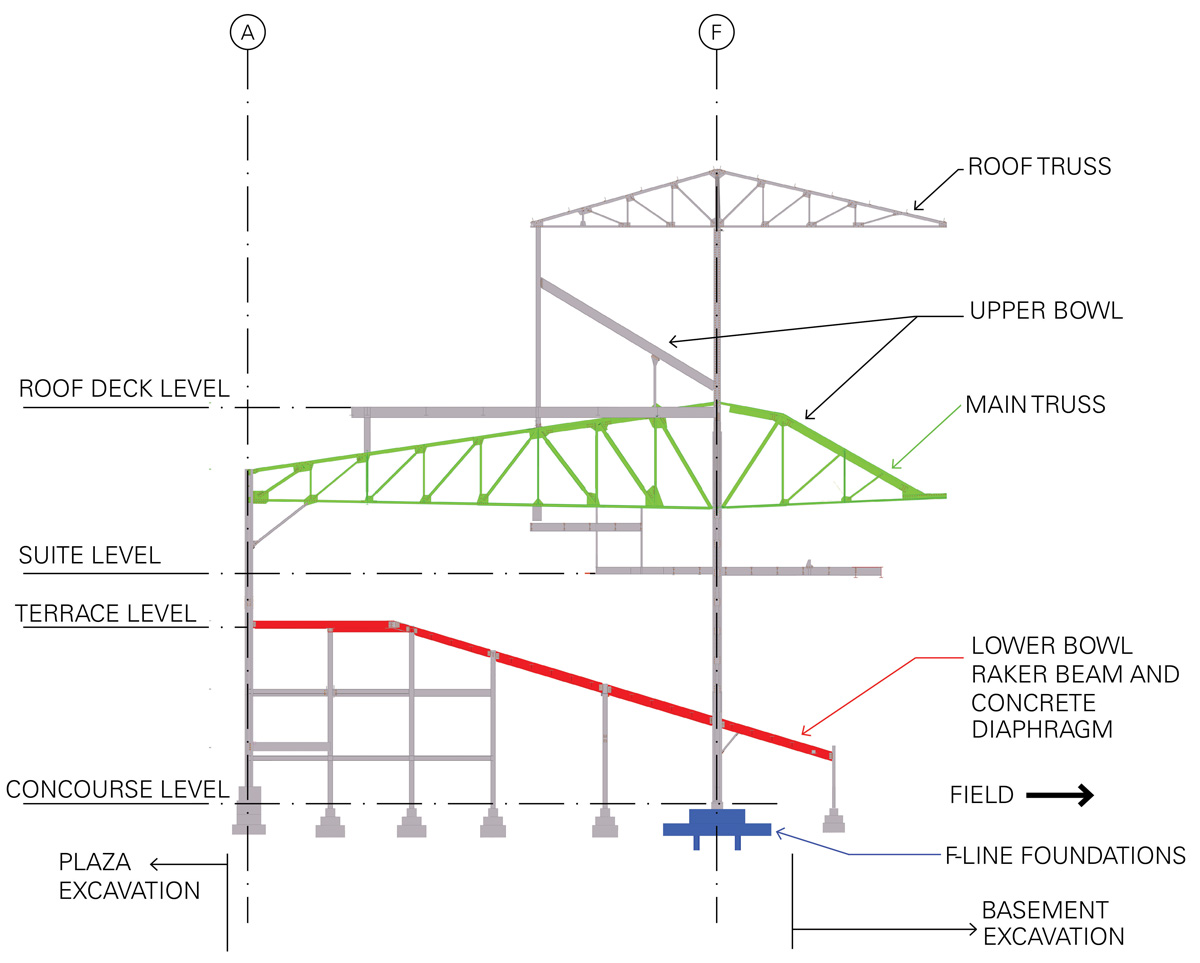
Figure 1. Typical cross-section of steel stadium structure.
The load above the terrace level, including the roof, upper deck, suites, and ramps, is carried only by the A-line and F-line columns, while a series of intermediate columns carry the load at the mezzanine and terrace levels. Most of the column footings not located on the A-line and F-line had to be enlarged to carry the additional vertical loads. Also, additional combined footings were required at new braced frame locations to complete the lateral load resisting system in the stadium.
To evaluate the site soil conditions, TT called to the pen for GEI Consultants, Inc. Their findings identified a high water table and sandy to clayey soil below the ground surface. Based on a combination of these findings, additional and higher loads in the new design, and the need to prevent undermining of existing shallow footings due to the adjacent excavations, it was determined that converting the shallow footings on the A-line and F-line to deep foundations using micro-piles was the most efficient way to strengthen them in lieu of enlarging or replacing them. The A-line footings adjacent to the plaza/office building excavation were tied together with a grade beam supported on micro-piles. The columns along A-line were connected with plates that were embedded inside the concrete curb on top of the grade beam. The remaining A-line footings, not adjacent to an excavated area, were enlarged based on the load carrying capacity required of them by the new program.
Significant corrosion found at the base of the F-line columns required a different approach to strengthen the existing footings. To address the issue of corrosion and to strengthen the existing unreinforced F-line column footings at the same time, a reaction frame and a shoring frame assembly were used to temporarily support each column and transfer the load down to new micro-piles. Initially, the existing footings were selectively drilled to allow for the installation of the micro-piles that provide support to the reaction and shoring frame assemblies. After the column was temporarily supported by the frames, the top of the existing footing was demolished to allow for repair of the corroded base of the column, and a new seat within the reaction frame was installed on which the column would bear. After the column was completely supported on the reaction frame, the shoring frame was removed and subsequently used at other F-line columns. The reaction frame assembly supporting the column was ultimately protected by embedding it in reinforced concrete. The different stages involved in the underpinning of the existing F-line footings are shown in Figure 2.
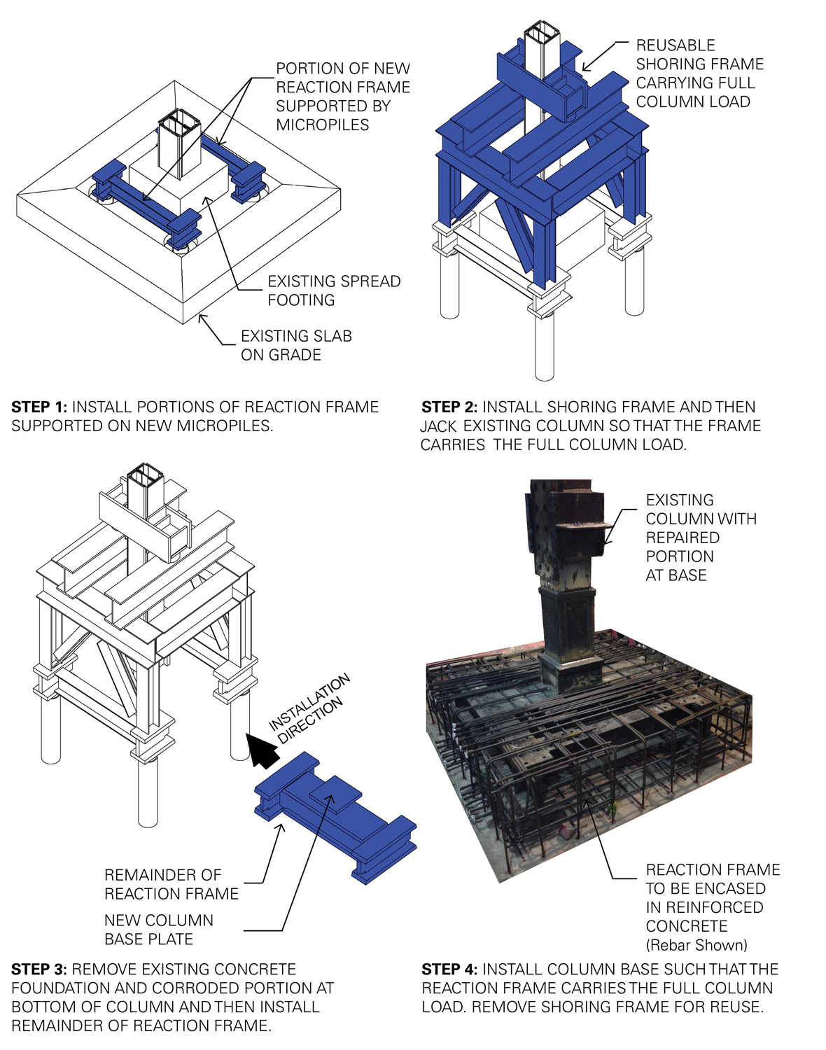
Figure 2. F-Line underpinning process.
Reinforcing Existing Trusses
The main trusses of the stadium span approximately 65 feet between the A-line column at the perimeter of the stadium and the F-line column adjacent to the concourse (Figure 1). A 30-foot cantilever projects past the F-line column towards the field. In the existing design, the trusses support the upper seating deck and roof above and the suites below. The renovation project includes expanding the suites and adding a roof deck open to fans during events.
The original trusses consist of relatively light double- and single-angle members ranging from 2½ to 6 inches deep connected by rivets at gusset plates. Reinforcement was required for both the individual members and the nodal connections to support the larger suites and new roof deck. Member capacity was increased through various combinations of faceplates welded to the angle webs or existing flanges and flange plates added to create I-sections.
The existing truss members were welded to the gusset plates so that shoring would not be required to lead off the node reinforcement process. These temporary connections were analyzed for the loads expected during the construction season when the stadium would remain unoccupied, but could potentially carry snow loads. Next, the rivets were removed through a process honed by the ironworkers, contractor, and design team to be time efficient and to maintain as much original base material as possible (Figure 3). Each rivet head was cut off; the shaft was then heated with a torch; and finally, the remaining rivet material was hammered out. Once the rivets were removed, any damage from the torching process was repaired and new “finger” gusset plates, shaped to align with the geometry of the truss members, were installed on each side of the assembly and fastened with high strength bolts. These plates were thicker than a typical gusset plate located at the center of the double angle members but had a lower visual impact on the overall appearance of the trusses.
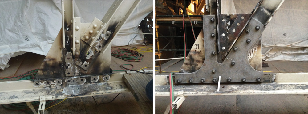
Figure 3. Truss node with truss members welded to gusset plate and rivets removed (left) and reinforced with new finger gusset plates and high strength bolts (right).
Creating a Diaphragm
TT’s review and analysis of the Wrigley Field structure indicated that the existing lateral system was ill-defined and unable to demonstrably withstand code-prescribed wind loads. To create a reliable lateral system, TT developed a scheme that would utilize the concrete deck of the lower seating bowl as a diaphragm.
The lower seating bowl construction is a patchwork of both cast-in-place (CIP) and precast concrete of varying ages. TT determined that these concrete sections were adequate to serve as a diaphragm, and independent testing concluded that the concrete had 40 to 50 years of service life remaining. However, the connection details at the end of the precast planks were unable to transmit the calculated diaphragm forces. Therefore, using the lower seating bowl as a diaphragm required a solution to create continuity between the CIP and precast concrete elements. Providing expansion joints would have been structurally difficult and architecturally undesirable, so a design was developed that could function without them.
The chosen solution was to create a concrete encasement around the steel raker beams supporting the CIP and precast concrete spans (Figure 4). In coordination with Chicago Landmarks Commission, the raker encasements were designed to be approximately 1 foot 6 inches deep by 3 feet wide utilizing CIP concrete. In addition to creating the diaphragm, the raker encasements allowed the design team to execute a triple play by addressing two other lingering design issues. First, due to increased loads imposed by other modifications to the stadium, the rakers themselves required strengthening. The raker encasements were designed to carry the full raker beam load, making the existing steel rakers redundant. Second, many of the precast planks had severe damage at their support points and required repairs. The raker encasements provided new end support for the precast planks by encapsulating the plank ends within the raker encasements.
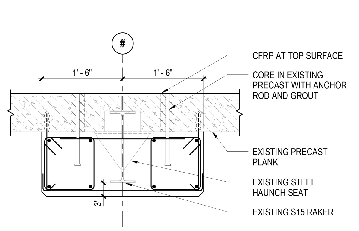
Figure 4. Schematic raker encasement detail.
Carbon fiber reinforcement was applied to the top side of the raker encasements to provide a complete load path to transmit diaphragm forces in tension. Compression forces were transmitted through non-shrink grout which was packed in the joints between precast planks.
Lastly, the effects of volume change in the new continuous diaphragm needed to be analyzed. Shrinkage was no longer a consideration because of the age of the precast. However, by locking all the concrete sections of the lower bowl together, thermal stresses became much larger than they were before implementing the repair. In fact, the thermal stresses controlled the design. Due to the shape of the stadium, thermal forces cause the diaphragm to try to open and close like a clamshell. The highest thermal forces in the diaphragm occur at the apex of this movement, behind home plate. Drag struts and related detailing were provided in these areas to carry the diaphragm chord forces.
Conclusions
The desired upgrades to Wrigley Field required innovative structural engineering solutions to economically and expediently strengthen the foundations and reinforce the superstructure of the iconic stadium. Despite being thrown a few curveballs, the repairs developed by the project team allowed Wrigley Field to maintain its iconic and historic character, with a structure to withstand the next 100 years of use.▪
A similar article was initially published online in ASCE’s Civil Engineer Magazine. The author has expanded on the topic and provided detailed information on the structural engineering involved in the project. Portions are reprinted with permission.
Project Team
Owner – Chicago Cubs
Owner’s Representative – CAA ICON
EOR – Thornton Tomasetti, Inc.
Architects – Populous; Stantec (formerly VOA Associates Inc.)
Contractor – Pepper Construction Group