
Most designers who engineer reinforced masonry know that code provisions for lap splice lengths have been evolving over the past few code editions. A newer confinement-steel option is available that has the potential to significantly reduce the lap splice lengths, especially for larger diameter bars, through confinement of the structural reinforcement.
Lap Splices and Constructability
Reinforced masonry typically has vertical bars cast in grouted cells and may have horizontal bars cast in bond beams or joint reinforcement placed in mortar bed joints. In reinforced concrete masonry walls, long vertical bars are problematic for masons if traditional closed-end blocks are used. The mason must lift the blocks over the bar that extends out of the previously grouted masonry, or over dowels extending out of the footing.
The use of lap splices improves the constructability of walls when using traditional, closed-end block (Figure 1). Lap splices allow the use of shorter vertical bars by transferring stresses from one reinforcing bar to another through the development of the splice. However, lap splices increase the total volume of reinforcement in a wall and can impact the cost of the project. Masonry contractors have estimated that 80% of laps occur at vertical bars. This is because long horizontal bars can be easily placed in bond beams with minimal splicing.
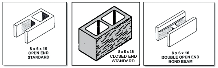
Figure 1. Concrete masonry units are manufactured with different web configurations. Closed-end units are most common, but open-end (“A”) or double open-end (“H”) units are available in some areas.
The constructability of a masonry wall and the ease of lap splicing is also impacted by the way the grout is placed. Walls can be grouted without clean-outs (typically called low-lift grouted) or grouted with cleanouts (high-lift grouted). In low-lift grouting, a short section of wall, up to 5 feet 4 inches high, is laid up prior to grouting. The reinforcement being lap spliced extends above the section being grouted, into the next section of wall to be constructed (Figure 2). In high-lift grouting, the wall can be laid to a maximum height of 24 feet prior to grouting. In this case, longer vertical bars can be placed before grouting and the number of lap splices is minimized.
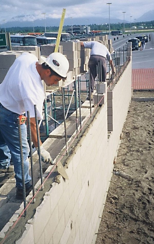
Figure 2. A new section of wall is getting started after grouting of the section below. The reinforcement being lapped extends into the next section of wall.
Horizontal reinforcing bars, placed in bond beams, may limit which grouting method is utilized due to grout flow concerns in partial-grouted walls. However, bond beams are mandated for areas of high seismicity and may be required for some designs in areas of low to moderate seismicity, especially if portions of the wall need to span horizontally. This may have the effect of negating the ability to use the higher grout pours. However, with the new confinement steel option described in this article, the horizontal bond beam steel may be used as confinement steel and can reduce the lap splice length required in the vertical reinforcement.
Lap Splices and the Codes
As wall heights, wind pressures, or seismic forces increase, larger reinforcing bars are required and larger bars require longer laps. When walls are taller in areas of higher wind and seismic forces, bars may also need to be offset from the centerline of the wall to increase the internal moment arm between the tension and compression forces. In some cases, this can significantly increase lap splice lengths and impact constructability.
The reinforced masonry design provisions found in the 2015 International Building Code (2015 IBC) reference the Building Code Requirements and Specification for Masonry Structures, TMS 402-13/ACI 530-13/ASCE 5-13 (TMS 402-13). The reinforced masonry design provisions found in the 2018 International Building Code (2018 IBC) reference the Building Code Requirements and Specification for Masonry Structures, TMS 402-16 (TMS 402-16). TMS 402-13 has lap splice length equations for allowable stress design (ASD) in Section 8.1.6 and lap splice length equations for strength design (SD) in Section 9.3.3. In TMS 402-16, these provisions have been harmonized between the two design methods and placed in Sections 6.1.5 and 6.1.6. In either edition of the masonry standard, the lap splice lengths calculated by these equations depend on the specified steel reinforcement yield strength, the specified masonry compressive strength, reinforcement size factor, the bar diameter, and a bar location factor, K. The bar location factor, K, is the smallest of the minimum cover, the clear spacing between adjacent bar splices, or nine times the bar diameter. Since the bar location factor is in the denominator of the lap splice length equations of the masonry standard, decreasing the bar location factor increases the lap length. For large bars placed off the centerline of the wall, these equations can produce large lap lengths.
For typical ASTM C90 masonry units and Type M or S mortar, TMS 402-13 increased the minimum specified compressive strength of masonry, per the unit strength method, to 1,900 psi. TMS 402-16 further increased this minimum specified compressive strength of masonry walls to 2,000 psi. Since the specified masonry compressive strength is in the denominator of the lap splice length equations of the masonry standard, increasing the specified masonry compressive strength decreases the required lap length.
Section 2107.2 of the 2015 IBC allows an alternative determination of lap splice lengths for ASD for No. 9 bars and smaller. This equation was originally printed in the Uniform Building Code. The lap splice lengths calculated by this equation are dependent on the bar diameter and the stress in the reinforcement. The 2015 IBC permits a 72-bar-diameter cap on SD lap splice lengths. The 2018 IBC includes this same cap for ASD.
Lap Splices with Confinement
The TMS 402-11 introduced a confinement factor for masonry lap splices calculated by either ASD or SD. When small diameter reinforcement is placed transversely, to cross both the top and bottom ends of a lap splice, the lap lengths calculated by either the ASD or SD sections of the masonry standard may be reduced due to confinement of the splice. The reduction can be significant but in no case can the reduced lap length be less than 36 bar diameters.
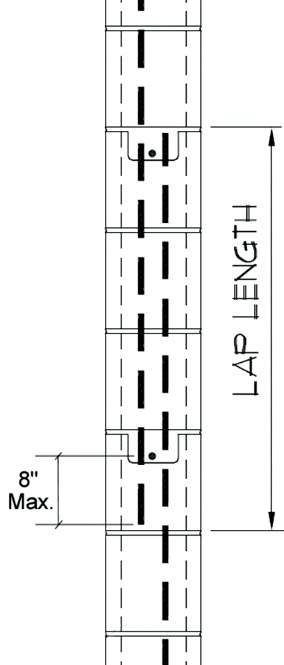
Figure 3. Confinement of the splice must include transverse reinforcement placed within 8 inches of each end of the lap.
This confinement factor was developed after extensive testing of lap splices with confining reinforcement by the National Concrete Masonry Association. The research found that the transverse, or confinement, reinforcement increases the lap performance significantly. The transverse bar must be No. 3 or larger placed within the last 8 inches of each end of the lap (Figure 3). Additionally, the clear space between the transverse bars and lapped bars may not exceed 1.5 inches, and the transverse bars must be fully developed in grouted masonry at the point where they cross the lapped reinforcement. Horizontal reinforcement in bond beams can be used to satisfy this requirement.
The authors have participated in masonry industry focus groups to discuss the implementation of this potentially beneficial confinement provision. It requires detailing the masonry lap splices and the location of the transverse confining bar on the design drawings. Even in masonry walls with closely spaced bond beams, most vertical bars only have a crossing horizontal bar at one or the other end of the splice, so an additional horizontal bar may need to be located at the top or bottom of the splice.
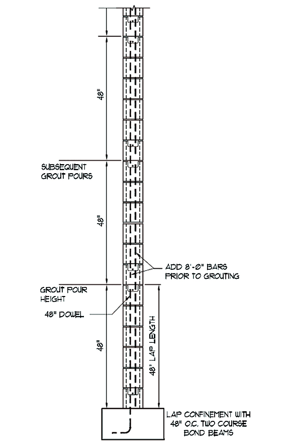
Figure 4. Double-height bond beams can be used as one option to properly confine a lap splice and reduce the required lap splice length.
The confining reinforcement does not have to consist of continuous horizontal bars; however, the confining reinforcement does have to be developed on each side of the spliced bars and grouted solid. Some proposed details have suggested short “pigtail” bars in grouted cells. While this would only need attention to placement in fully grouted reinforcement, it is more problematic in partially grouted masonry because it requires additional consideration of blocking off cells to grout occasional adjacent horizontal cells. Details have been produced which have double bond beams at the tops of grout placements. This provides horizontal bars, in adjacent horizontal courses, at the top of one end of a splice and the bottom of the end of the adjacent splice (Figure 4). The implication is that all splice lengths need to be the same length and bond beam spacing is set by the splice length or vice versa. Because reinforced masonry walls typically have different sized bars at the ends of shear walls than those that are present in the field of the wall, this approach also requires additional detailing. If the splice lengths can be standardized and set to a single length, another alternative would be to place intermediate bond beams between typically spaced bond beams to confine the upper end of all the spliced bars (Figure 5). The reduction in lap lengths can be significant. The reduction in the amount of vertical reinforcement required for laps, as well as the ease of construction with shorter laps and the resulting cost savings, can offset the additional horizontal confining steel and grout, especially with the thoughtful use of required bond beams.
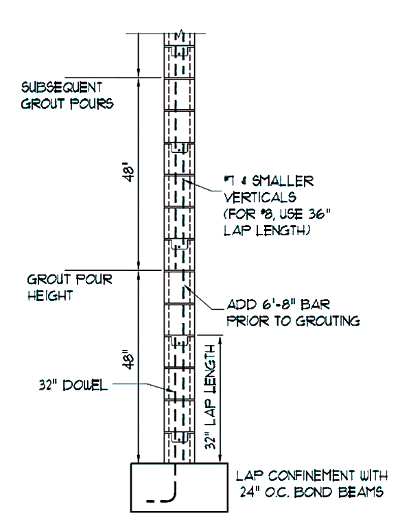
Figure 5. The use of intermediate bond beams is another option to confine a lap splice properly. The splice length can be standardized for various bar sizes depending upon the bond beam spacing.
Which Approach Should You Use?
So what approach should be used to determine lap splice lengths? The authors have several observations:
- The most economical masonry construction typically uses the shortest laps.
- Keep the lap length shorter than or equal to the grout placement height. Otherwise, there will be three vertical bars in the lap region in some locations, potentially causing grouting congestion.
- If open-ended units are available, they may improve constructability.
- When solid grouting walls, consider using more frequent, smaller vertical bars with shorter laps.
- If you are using the 2015 IBC and TMS 402-13 for concrete masonry design, standardize on a specified masonry compressive strength, f´m, of 2,000 psi now, rather than increasing to 1,900 psi now and 2,000 psi in the next cycle. That way, in most cases, you will only need to update your structural notes, typical details, and splice length tables once.
- For reinforcing bars centered in 8-inch CMU or thicker walls of typical strengths, with bar sizes up to No. 6, the equations from either the 2013 or 2016 edition of TMS 402 will produce the shortest lap lengths.
- For offset bars up to No. 5 in typical 8-inch CMU walls, try to use a minimum cover of 2.0 inches and the equations from either the 2013 or 2016 edition of TMS 402.
- For No. 6 offset bars in CMU walls, try to use a minimum cover of 2.5 inches, the maximum grout lift height of 5 feet 4 inches, and the equations from either the 2013 or 2016 edition of TMS 402.
- If the minimum cover of 2.0 inches for No. 5 bars and 2.5 inches for No. 6 bars isn’t feasible, or if the bar size is equal to or larger than No. 7, you can either use the lap splice equations from the IBC or use the confinement equations from TMS 402 with special job specific detailing.
- If you are using the confinement equations from TMS 402 and have bond beams, use a bond beam spacing of 48 inches on-center, 32 inches on-center, or 24 inches on-center.
Splicing of reinforcement in masonry walls allows for efficient construction. If low-lift grouting is being used, the use of shorter length vertical reinforcing bars (7 to 10 feet) saves on labor costs. Reinforcing bars may be spliced by lapping, as discussed in this article, by mechanical splices, or by welding. Lapping bars is the most common splicing method and using confinement reinforcement is the latest design option.
Since the use of confinement of lap splices is still a relatively new provision, the authors welcome feedback on specific job details developed and information on how the mason contractor responded to the detail, as well as how the use of confined lap splices impacted the project.▪