
Your client has proposed a building where the exterior steel beams and columns are painted and exposed but the portal space is filled with concrete masonry. Your first thought may be, “Wow, that is a lot of extra building mass to deal with!” Immediately after that thought might come a series of questions. “I wonder if there is a way to use that masonry, instead of it just being along for the ride? Where would I look for design guidance?” The short answers to those questions are yes, you can make use of the masonry and answers are available in the Building Code Requirements for Masonry Structures (TMS 402). This article expands on those answers and additional questions that might arise during the design process.
Infill Behavior
The proposed system is specifically called a masonry infilled frame, and they are far from new. Thousands of masonry infilled frames have been constructed in the United States and internationally over the last century. Unfortunately, many of those designs did not take into consideration the complexity of the behavior of the masonry when it is bounded by an external frame. First, it would be wise to explore the behavior of masonry infills as they are loaded with in-plane forces.
Several stages of response occur during the in-plane loading of a masonry infilled frame. Initially, the system acts as a monolithic cantilever wall. Slight stress concentrations occur at the four corners, while the middle of the panel develops an approximately pure shear stress state. As in-plane loading continues, separation occurs at the interface of the masonry and the frame members at the off-diagonal corners. Once a gap is formed, the stresses at the tensile corners are relieved while those near the compressive corners are increased.
As the load continues to increase, further separation between the masonry panel and the frame occurs, resulting in contact only at the frame sections near the loaded corners. This condition of contact results in the composite system behaving as a braced frame. This has led to the concept of replacing the masonry infill with an equivalent diagonal strut when modeling the behavior of the system (Figure 1; gaps are highly exaggerated). The induced stresses in the masonry panel produce various cracking patterns depending on the combination of the shear strength of the mortar joints, the tensile strength of the masonry units, and the relative values of the shear and normal stresses.
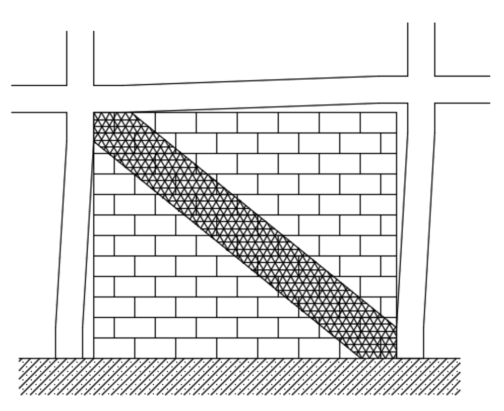
Figure 1. Equivalent strut.
Failure of masonry infilled frames can be classified into three basic modes: shear cracking, compression failure, and flexural cracking. Shear cracking can be divided into cracking along the mortar joints, which includes stepped cracks and horizontal cracks, and diagonal tensile cracking. The compression failure mode consists of the crushing of the masonry in the loaded diagonal corners and the failure of the diagonal strut. The diagonal strut is developed within the panel as a result of diagonal tensile cracking. Flexural cracking failure is rare because separation at the masonry-frame interface usually occurs first; then, the lateral force is resisted by the truss mechanism of the diagonal strut. Figure 2 shows the development of the diagonal strut using stepped loads in an ANSYS finite element analysis investigation. The upper left corner is the application point for the in-plane load with the load increasing from top to bottom in Figure 2. Note that the compressive stresses propagate from the loaded corner to the opposite diagonal corner. As the loading level increases, the compressive stresses in the confined corners also increase.
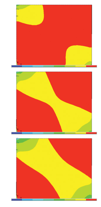
Figure 2. Strut development as load increases.
When loaded out-of-plane, masonry infills develop a three-hinged arch, which resists these out-of-plane loads. Figure 3 shows the development of such an arch. Small gaps (exaggerated in Figure 3) form on the loaded side of the infill between the infill and the bounding frame. Tensile stresses on the opposite face of the masonry cause a longitudinal crack to develop. The out-of-plane load is then resisted by compression in the masonry at the hinge locations. It should be noted that this arching can, and often does, develop as two-way arching. The Code equations presented later are based on two-way arching of the masonry infill material.
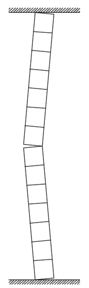
Figure 3. One-way arching of infill.
TMS 402 Design Guidance
The 2011 TMS 402 added Appendix B, “Design of Masonry Infill,” to provide mandatory language to allow the designer to use masonry infill effectively. The 2013 and 2016 TMS 402 further developed those code provisions. These provisions address participating infills and non-participating infills for both in-plane and out-of-plane loading conditions, as well as limitations to the usage of masonry infills. Concrete masonry, clay masonry, and AAC masonry are all permitted as infills. Non-participating infills are required to be isolated from the surrounding frame, so as not to impart additional loads to the frame members that might cause localized failure to occur. For instance, infills that do not extend the full height of the column are prohibited from use as part of the lateral-force-resisting system due to the creation of short columns, which have historically performed poorly in seismic events. Currently, infills with openings are also prohibited; however, the current TMS 402 committee is considering code language to address small openings and their effect on the behavior of the infilled frame system.
TMS 402 Section B.3.5 also gives direction for the design of the bounding frame members. The bounding frame is obviously designed using the appropriate material code; however, TMS 402 recommends a ten percent increase in the design shear and moment loads established from the equivalent strut braced-frame analysis.
Design Example
Consider a masonry infilled frame with the following properties. The infill is constructed of nominal 8-inch concrete masonry units, f´m = 2,000 psi, and Type S PCL mortar. Assume hollow units with face-shell bedding only (mortar on the face shells of the units only). The total wall height measures 14 feet 10 inches to the roof, with the infill 14 feet in height. The bounding columns are W10x45s oriented with the weak axis in the plane of the infill (Ibc = 53.4 in.4 weak axis and Ibc = 248 in.4 strong axis) and are spaced at 32 feet. The bounding beam above the masonry infill is a W10x39 (Ibb = 209 in.4 weak axis and Ibb = 45 in.4 strong axis) and carries only minimal roof loads. The infill is mortared tight to the bounding frame on all sides. The infilled frame is loaded with a wind load of 35 psf calculated per ASCE 7-10 with a 20-foot tributary area, resulting in a total unfactored in-plane load of 5,191 pounds. Using the conservative loading case of 0.9D + 1.0W leaves the in-plane load at 5,191 pounds.
In-plane Design
Section B.3.1.1 limits the nominal height-to-thickness ratio to 30. The ratio for this infill is:
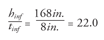
The height-to-thickness ratio is less than the maximum of 30 and is therefore accepted as a participating infill.
Calculation of the equivalent strut width is carried out using TMS 402 Equations B-1 and B-2a for concrete masonry and clay masonry, and TMS 402 Equation B-2b for AAC masonry.
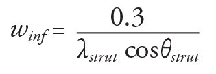
where
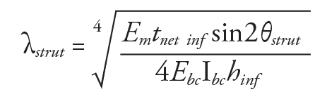
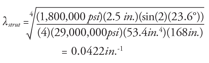
The characteristic stiffness parameter, λstrut, is a measure of the relative stiffness of the bounding frame and the masonry infill. θstrut is the angle of the diagonal of the infill measured with respect to the horizontal, which is 23.6° for this infill. The net thickness of the infill, tnet inf, is 2.5 inches for this ungrouted infill. The characteristic stiffness parameter is then:
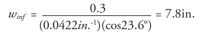
The equivalent strut width is then:
TMS 402 Section B.3.4.3 states that the nominal shear strength of the infill shall be the least of Equation B-3, the horizontal component of the force in the equivalent strut at a horizontal racking displacement of 1.0 inch, or the smallest nominal shear strength from TMS Section 9.2.6.1 calculated along a bed joint. TMS 402 Equation B-3 is an empirical equation developed by Flanagan and Bennett in the late 1990s:
Vn = ((6.0in.)tnet inf)f´m
TMS Equation B-4 and Section 11.2.5 are used when the infill is composed of AAC masonry. For this example, Vn (based on TMS 402 Equation B-3) is:
Vn = (6.0in.)(2.5in.)(2,000psi) = 30,000lb
The stiffness of the equivalent braced frame is determined by a simple braced frame analysis where the stiffness is based on the elastic shortening of the diagonal strut. The strut area is taken as the width of the strut multiplied by the net thickness of the infill.
The equivalent braced frame stiffness is:
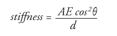
where d is the diagonal length of the infill. For this infilled frame the stiffness is:
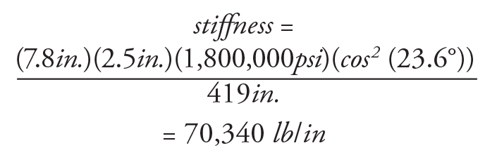
At a horizontal racking of 1.0 inch, the nominal shear strength is the stiffness multiplied by 1 inch and is thus 70,340 pounds.
The applicable sections of TMS 402 Section 9.2.6.1 are Equations a, b, and c. These yield nominal shear values of 163,144 pounds, 288,000 pounds, and 53,760 pounds, respectively, where the compressive force normal to the shear surface was conservatively taken as zero.
The least of these nominal shear values is 30,000 pounds from TMS 402 Equation B-3. Using the strength-reduction factor of 0.6, as mandated by TMS 402 Section B.1.4, results in a design shear capacity of 18,000 pounds, which significantly exceeds the factored design shear of 5,191 pounds and the infill is satisfactory for shear. As previously mentioned, TMS 402 Section B.3.5 requires the designer to consider the effect of the infill on the bounding frame and to increase the shear and moment results from the braced frame analysis by ten percent.
Out-of-plane Design
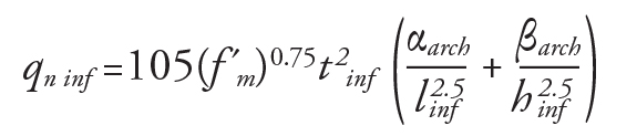
TMS 402 Section B.3.6 provides equations for the nominal out-of-plane flexural capacity. TMS 402 Equation B-5a requires that the flexural capacity of the infill be:
where:
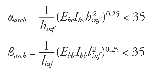
If a side gap is present, αarch is taken as zero, while a top gap requires βarch to be taken as zero. In addition, tinf shall not be taken greater than 1/8hinf. TMS 402 Equation B-5b is used for AAC masonry infill. For the example infill:
therefore,
Again, using the strength-reduction factor of 0.6 from TMS 402 Section B.1.4, results in a design flexural capacity of 37.6 psf, which exceeds the factored design wind load pressure of 35 psf and the infill is satisfactory for out-of-plane flexure.
Conclusion
Masonry infills are an efficient structural system for resisting lateral loads. Their construction is simple; the bounding frame is erected first, then the portal space is infilled with masonry resulting in a composite system. This allows for a staged, but rapid, construction sequence. As seen in the design example, masonry infills are capable of withstanding significant loads. So, when your client suggests a masonry infilled frame, you can be ready to take on this design challenge. Be sure to take advantage of the inherent strength of masonry, refer to TMS 402 often, and happy infilling!▪