
Exterior Non-Load Bearing Cold-Formed Steel Walls
The DoD Unified Facilities Criteria (UFC) program developed documents to assist in determining the design basis threat and the desired level of protection of structures. Determining the level of protection to be achieved by a building against an explosive threat can be complicated and is based on analysis that considers variables such as the value of assets inside the building, likelihood of aggressor attack, aggressor tactics, and threat severity. An engineer designing for Antiterrorism (AT) must have an understanding of how to perform a blast analysis. The focus of this article is blast protection of exterior cold-formed steel framing (CFS) in the building envelope with controlled perimeters subject to air blast.
The Unified Facilities Criteria 4-010-01
Federally-funded research programs led to the creation of design manuals for blast-resistance, such as TM 5-1300 which has since been superseded by the 2008 UFC-340-02, Structures to Resist the Effects of Accidental Explosions, and UFC 4-010-01, DoD Minimum Antiterrorism Standards for Buildings, published in 2013. UFC 4-010-01 was created with the overarching goal of minimizing the likelihood of mass casualties from terrorist attacks against DoD personnel inside routinely occupied buildings. Though developed for DoD use, many private sector projects utilize the UFC 4-010-01. Current design guidance for blast loads is scarce, making the UFC 4-010-01 an extremely valuable document. The levels of protection described within UFC 4-010-01 are adequate to meet the goal of minimizing the likelihood of mass casualties. It establishes a foundation for additional protective measures in higher threat environments. When confronted with design basis threats (explosive weights) more severe than outlined by UFC 4-010-01, the designer should consult UFC 4-020-01. Most UFC documents can be downloaded for free from the Whole Building Design Guide website, www.wbdg.org.
Unless adequate standoff distance can be provided, the UFC 4-010-01 applies to all DoD inhabited buildings, billeting, high occupancy family housing, and all DoD expeditionary and temporary structures. Existing buildings that do not meet prescribed standoff distances are required to meet the requirements set forth by UFC 4-010-01 when the building undergoes a renovation, modification, repair, or restoration that exceeds 50% of its replacement cost. When any of the above types of work are done to an existing facility, and the cost does not exceed 50% of the replacement cost of the building, the requirements of UFC 4-010-01 are merely a recommendation and not a requirement. Other types of work or types of structures that may trigger the requirements of UFC 4-010-01 are listed in section 1-8 of the document.
Standoff Distances
Conventional construction standoff distances are outlined in Tables B-1 and B-2 in Standard 1 of UFC 4-010-01. Baseline explosive weights are outlined in Table B-1 as explosive weights I and II. Explosive weight I is physically too large to be carried by an individual and is assumed to be delivered by a vehicle. There is high confidence that the quantities of explosives given by explosive weight I would be detected during a vehicle search and the designer should understand that the standoff distance associated with a controlled perimeter is based on this case. Explosive weight II is representative of a hand placed explosive. Hand placed explosives cause significant localized damage, and the assumption is that there will be controls in place to prevent them from being brought into the building. Failure to meet specified minimum standoff distance will trigger a blast analysis per UFC 4-010-01. It is essential to understand that the standoff distances listed in Tables B-1 and B-2 are based on the analysis of details commonly associated with various types of construction. For cold-formed steel (CFS) stud walls, the reader should consult Table 2-3, Conventional Construction Parameters, to ensure that the structure in question falls within the ranges of properties listed. Any construction outside the ranges listed in Table 2-3 will trigger the need for a blast analysis. Also, note that UFC 4-010-01 address only Very Low and Low Levels of protection against explosive weights I and II. The US Protective Design Center (PDC) Technical Report 10-02 should be consulted for higher levels of protection.
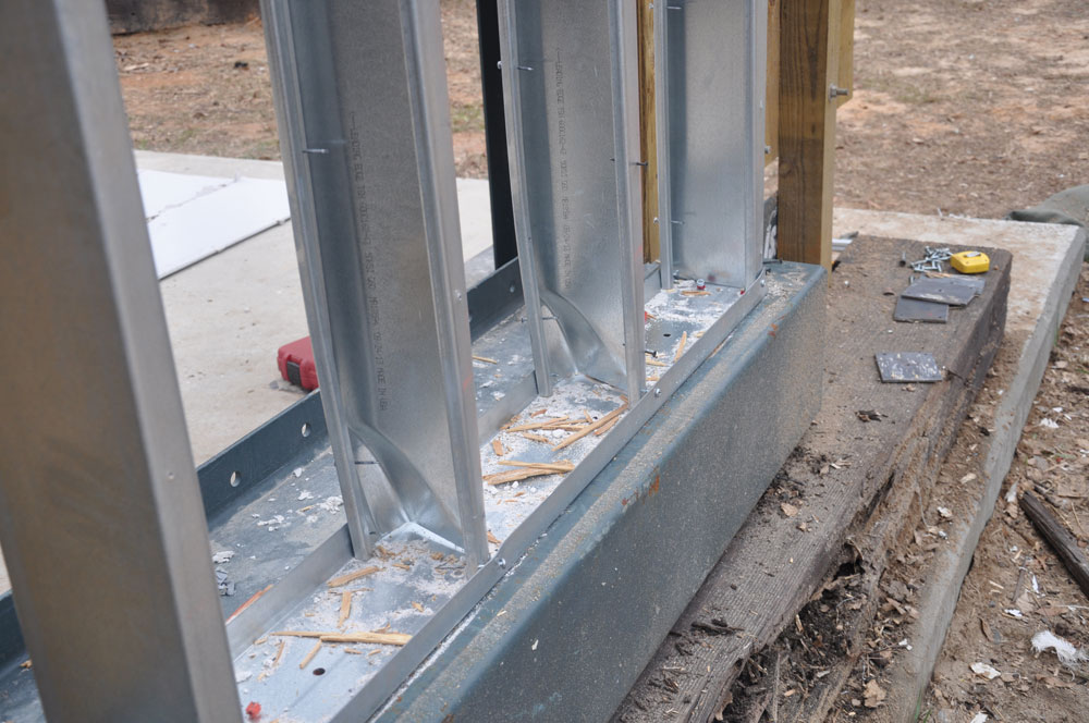
Figure 1. Blast load end of stud connection.
Research, development, testing, and evaluation of CFS stud wall systems exposed to blast continue today. Research studies on standoff distances and performance of stud wall end connections, similar to the test shown in Figure 1, have facilitated the development of improved designs. A recent PDC Technical Report 15-01, Minimum Standoff Distance for Non-Load-Bearing Steel Stud In-Fill Walls, provides reduced prescriptive standoff distances and construction criteria. These data were developed from numerical analysis and validated with lab tests for in-fill sheathed walls with end connections to structural concrete detailed with additional anchorage, as shown in Figure 2. When using these prescriptive standoff values, designers should carefully review construction criteria and connection details to ensure compatibility with project application.
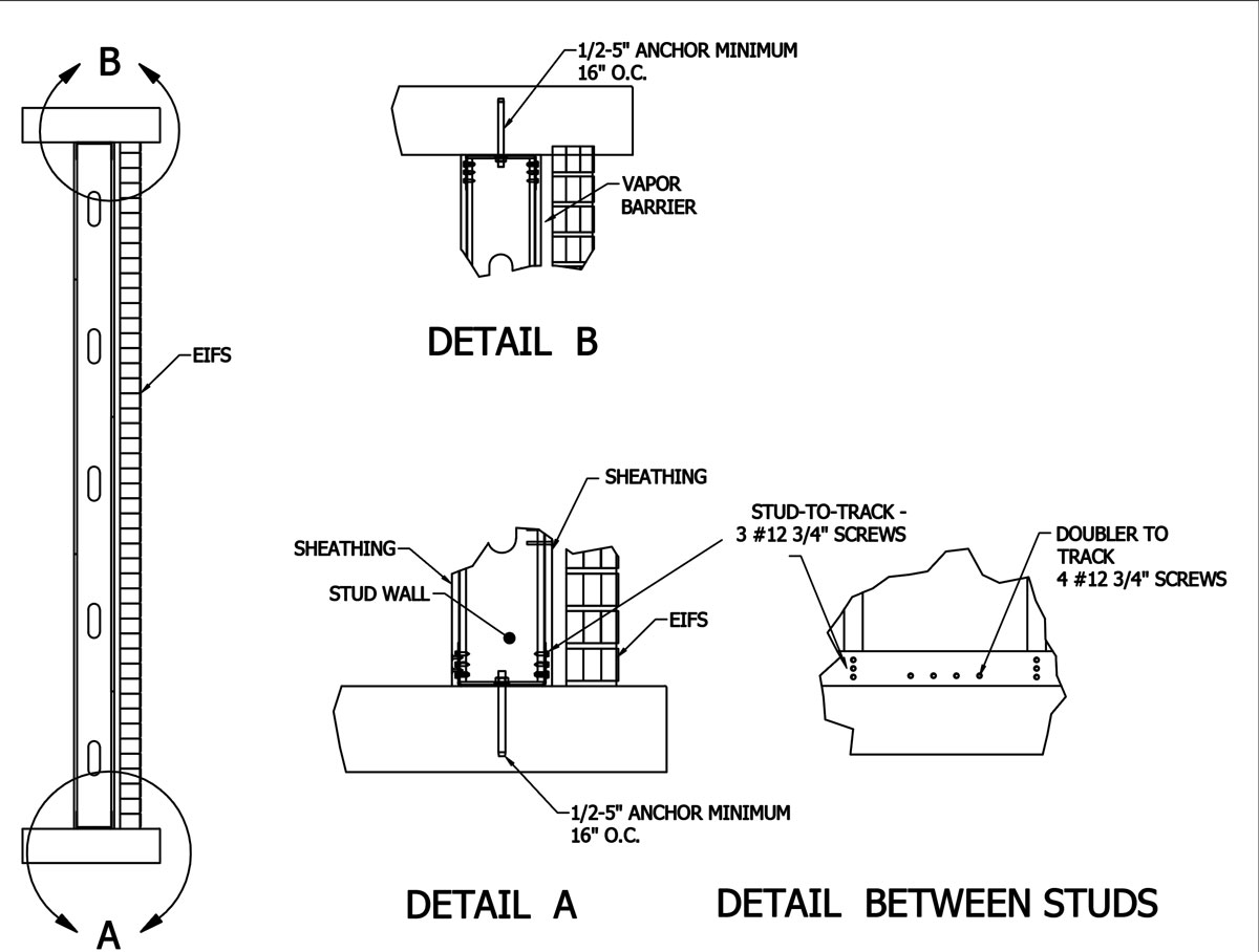
Figure 2. Prescriptive wall design SSW1 (Edited from PDC TR-15-01).
Windows, Skylights, and Louvers
Standard 10 of UFC 4-010-01 deals with the design of window openings in exterior walls. The standard states that blast analysis (using explosive threats provided in Standard 1) should be performed for the supporting structural elements of windows and their connections at all standoff distances, even if the wall meets or exceeds the conventional construction standoff distance. Where a building is within a controlled perimeter, the applicable explosive weights shall be determined based on the standoff from the controlled perimeter. Louvers may not need to be treated as windows if they are designed to remain open at all times. The structural designer should consult with the design team and DoD authority for clarification.
Design Approaches
Standard 10 of UFC 4-010-01 provides two design approaches to size the supporting structural elements of exterior window openings subjected to blast loads.
Static Design Approach
The static design approach is a direct, simplified method to determine the required moment and shear strengths of the jamb, header, and sill that frame the opening. However, this approach is only allowed if the conventional standoff distance to the wall is met and it can only be used for punched openings. A punched opening is bound by a header, a sill, and two jambs, and has façade material on all four sides.
In the static design approach, a tributary area increase factor (C) is calculated as:
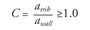 where awall is the tributary area for the typical conventional wall section (the typical stud), and atrib is the combined tributary area for the supported window and wall section. The required moment and shear strengths are calculated as:
MSSE = C.MCW
VSSE = C.VCW
where MSSE and VSSE are the required moment and shear strength of the supporting jamb, header, or sill, while MCW and VCW are the moment and shear strength of the conventional wall stud section. The static approach is limited to punched openings since it uses the tributary area of the typical wall stud to calculate the factor C. The end connections of the supporting structural element shall be designed for a load equal to the increased member shear capacity (VSSE).
Dynamic Design Approach
Typical CFS stud walls and the supporting structural elements of a window opening can be designed for the appropriate blast pressure, impulse, and duration using dynamic analysis. The design loads are determined from the applicable explosive weight at the actual standoff distance and should be applied over the areas tributary to the element being analyzed. A simple dynamic approach recommended by the UFC is the single-degree-of-freedom (SDOF) analysis. In the SDOF, the structural element is modeled as an equivalent mass-spring system. The mass and dynamic load of the equivalent system are based on the structural element mass and blast load, respectively. The spring stiffness and yield load are the flexural stiffness and out-of-plane flexural capacity of the structural element, respectively. The flexural capacity includes the effects of the Static Increase Factor (SIF) and the Dynamic Increase Factor (DIF) applied to the element’s minimum yield strength. The SIF accounts for the difference between the specified minimum and expected actual yield strength, while the DIF accounts for high strain rate effects when the element is loaded dynamically. The recommended SIF and DIF values for cold-formed steel are summarized in Table 1.
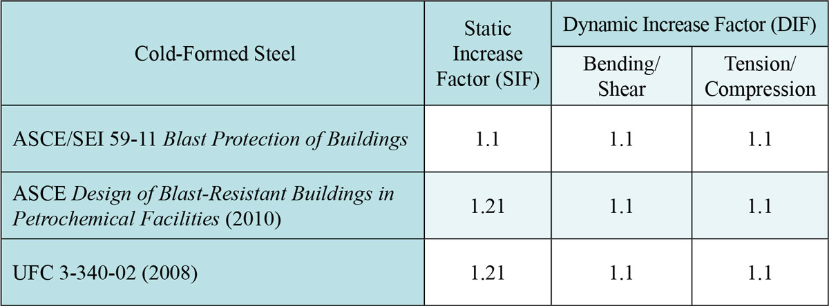
Table 1. Static and dynamic increase factors for cold-formed steel members.
In order to accept or reject the results of the SDOF analysis, response criteria should be defined. PDC-TR 06-08, SDOF Structural Response Limits, gives the response criteria limits in the form of maximum ductility ratio (μ) and maximum support rotation (θ). Table 2, which is part of PDC-TR 06-08 Table 4-6, shows the maximum allowed μ and θ for steel studs with various end connection conditions. Notice that the response criteria limits are dependent on the allowed damage level of the element. The damage level is a function of the Level of Protection (LOP) assigned to the structure, and whether the element is primary, secondary, or non-structural. For example, a gravity load-bearing element is a primary element while a curtain wall lateral load bearing element is a secondary element. The relationship between the LOP and element damage level is given in PDC-TR 06-08 Table 3-2. The response criteria limits in Table 2 are relatively stringent due to the limited capacity and ductility of conventional CFS framing systems in addition to limited test data.
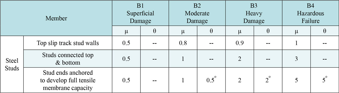
Table 2. Flexural response limits for cold-formed steel (From Table 4-6 in PDC-TR 06-08).
Exterior CFS studs and opening jambs are categorized as top slip track stud walls if a single or double slip track detail is used to attach the stud or the jamb, at their top ends, to the structure (Figure 3a). This connection detail does not provide a direct mechanical attachment between the stud and the top track; therefore, it is assigned a relatively low ductility ratio. However, exterior CFS studs and jambs can be categorized as studs connected top & bottom if a slip connector or a slip track detail is used to attach the stud or the jamb at their top end to the structure, as shown in Figures 3b and 3c. This provides mechanical attachment between the stud and the top track and, therefore, it is assigned a higher ductility ratio. The same ductility ratio can be used for exterior CFS by-pass studs and jambs if the member spans across at least three supports.
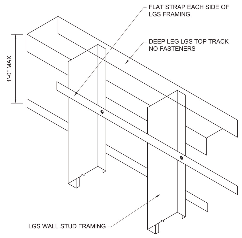
Figure 3a. Top slip track with no mechanical attachment.
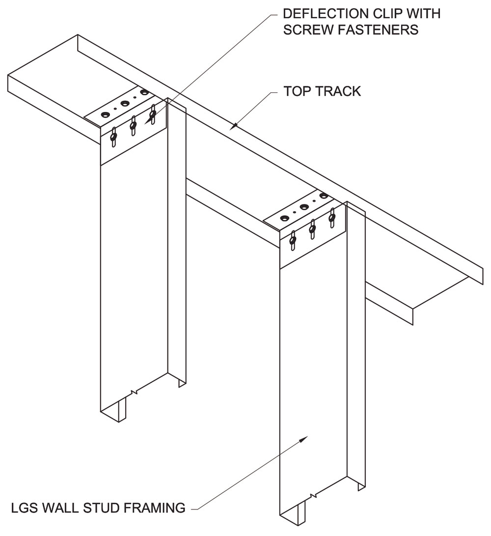
Figure 3b. Top slip connector with mechanical attachment.
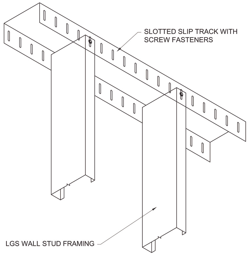
Figure 3c. Top slip track with mechanical attachment.
The PDC offers an Excel-based tool to design structural components with applied dynamic loading using the SDOF approach. The tool is called Single-degree-of-freedom Blast Effects Design Spreadsheet (SBEDS) and is available online at www.pdc.usace.army.mil/software/sbeds after obtaining approved access.
The top and bottom connections of wall studs and window jambs are designed for the peak reaction of the member. Note that, if the resulting ductility ratio (μ) of the member is less than 1.0, the member did not reach its yield limit in flexure and it is, therefore, permissible to reduce the design peak reaction by the value of the ductility ratio. Connector and fastener strength are conservatively recommended to be calculated based on their nominal resistance and appropriate code strength reduction factors (φ). The connection design shall account for all potential failure modes for the given connection type and base material.
Regardless of whether the static or dynamic design approach is used, the reaction forces from the CFS studs or window jambs do not have to be carried through the horizontal bracing system or floor diaphragm as long as the mass of the building can dissipate these reactions before they are transferred to the foundation. However, if the stud wall does not have a direct path to a bracing system or a diaphragm, then a path needs to be created for the reaction until it is dissipated into a massive element.
Summary
This article introduces antiterrorism design requirements and various analysis processes for exterior CFS stud walls. The UFC 4-010-01 provides measures to establish a required level of protection against terrorist attacks for all DoD buildings. Conventional construction parameters and conventional construction standoff distances for CFS stud walls are established in UFC 4-010-01. Exterior CFS walls meeting the requirements for conventional construction parameters and standoff distances do not require blast analysis. However, blast analysis should be performed for the supporting framing elements of windows and their connections, at all standoff distances. For a numerical design example illustrating the detailed blast analysis and design of a CFS exterior non-load bearing wall and the Jamb member of a punched window opening, refer to Cold-Formed Steel Engineers Institute TN S100-16, www.cfsei.org. It shows that the dynamic design approach for CFS stud walls is more economical and is, therefore, recommended over the static design approach.▪