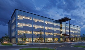
Trimble Rockies Campus Positioned to Deliver Impressive Efficiencies, Innovation
Trimble Navigation is best known as a leader in positioning technologies that help the world’s mobile workforce build, harvest, map, plan, and survey everything from the Beijing National Stadium to the mineral mines of South Africa. So when company executives decided to build – rather than lease – new office space to support the over 500 engineering, marketing, and sales staff based in Westminster, Colorado, they understandably believed their positioning technologies could help optimize people, processes, and materials in the built environment.
The Rockies Campus project offered Trimble a particularly unique opportunity to demonstrate the potential of its positioning, information sharing and collaboration BIM solutions to deliver a new office space with greater speed and improved communication, along with all the coordination opportunities that a project team could envision.
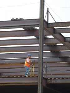
With BIM-to-field connections, the project team achieved 100% embed placement and had zero placement errors during steel frame layout.
Lean and Green
Designed by OZ Architecture in Denver, Colorado, the four-story, 125,000-square-foot Trimble Rockies Campus incorporates floor-to-ceiling windows for abundant natural light and spectacular views of the Rocky Mountains and downtown Denver skyline. There is extensive bike parking with access to regional trails and large locker rooms to encourage exercise. With the goal of LEED Silver certification, the building envelope is optimized for energy performance using passive systems that do not use any man-made energy to function once installed; only natural free energy. The overall energy cost savings over an ASHRAE 90.1 2007 building is at least 30%. Water use was reduced by 40% as compared to a typical building of its size.
For JE Dunn, the general contractor, the challenge was to complete the structure in 13-months or less using the latest collaboration and information sharing technologies to support design, sitework, fabrication, and construction.
To meet the fast-track schedule and owner requirements for collaborative technologies, such as BIM, the project team implemented integrated project delivery (IPD) strategies to streamline all facets of the project.
The BIM Execution Plan called for architectural, structural, mechanical, electrical, plumbing, fire safety, and accessibility designs to be completed using BIM design tools. The building model would be used to facilitate design coordination, conflict checking, constructability reviews, and store building component specification data.
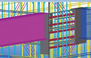
In-model review tools helped drive discussion during and resolve potential conflicts in advance of fabrication and steel erection.
AIA Level of Development (LOD) requirements were assigned for structural, fire protection, and mechanical, electrical and plumbing (MEP) BIM. In order for all MEP trades to utilize the same model for coordination and fabrication, the team modeled the building systems to a LOD 400, which includes enhanced levels of detail that pertain to specific MEP systems, such as pipe hangers, fittings, and junction boxes.
The availability of one digitally and dimensionally accurate model for design and construction coordination, detailing, fabrication, and field level management would create opportunities for workflow efficiencies throughout the design and construction of the structure. In addition, the general contractor applied “Lean” principles throughout to streamline workflows.
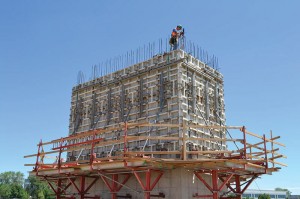
Lean principles and BIM-to-field connections facilitated significant efficiencies during the construction of the structure’s two stair cores and elevator core.
The formwork lift drawings were coordinated in the 3D model with rebar, embeds, anchor studs, beam form pockets, and blockouts. During field installation, the formwork, rebar, and embeds were continuously checked for accuracy with the Trimble robotic total station, per the 3D model. Embeds were color coded based on positioning/orientation in the wall to allow efficient installation. After the concrete work was complete and the steel structure was erected, the general contractor found that embeds were installed with 100% accuracy.
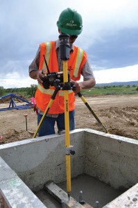
During field installation, the anchor bolt placements as well as formwork, rebar, and embeds were continuously checked using Trimble’s Robotic Layout Solution – Trimble Field Link for Structures and verified in the Tekla Structures model.
Accuracy Drives Quality
JE Dunn hired Zimmerman Metals, a steel fabricator proficient with Tekla Structures, to help create synergy in the steel design, fabrication, and delivery.
With the intent to reduce duplication of effort, the general contractor, the structural engineer (Structural Consultants, Inc. or SCI), and the steel fabricator opted to use one federated model developed in Tekla Structures from design through construction to expedite steel delivery. The idea was that the same model that is used to permit approved contract documents is leveraged to detail and fabricate shop drawings for rebar, structural steel, exterior metal studs, and structural components.
SCI detailed the rebar shop drawings and adapted its Tekla Structures model to the rebar fabricator’s standards and installer’s constructability comments.
Two charettes were conducted with all parties to optimize embed locations and shift rebar as needed to accommodate anchor studs. This collaboration effort streamlined and expedited the review/approval and material procurement processes.
During erection planning, the fabricator set up a truck delivery schedule based on the Tekla Structures model. A trailer load of steel was scheduled every four days. Due to the accuracy of the steel from the BIM, the erector set the first load in 1.5 days. Since the next shipment of steel did not arrive for another 1.5 days, the erector proceeded to finish all bolting, decking and welding on the first load of steel.
The set, bolt, and weld sequence continued for every subsequent load of steel. The “back welding”, typically completed after the frame is erected, happened concurrent with the erection schedule. Expedited steel erection enabled the concrete decks to be poured sooner.
The steel was originally scheduled to be erected in 10 weeks, not including complete bolting and welding. Based on the described sequence and accuracy of steel placement, the entire steel structure was completed in 10 weeks.
The use of BIM also allowed the steel erector to cut the anticipated splice plate correction work by 50% due to the accuracy of the steel members and concrete work. Overall, the steel structure resulted in 67% fewer RFIs and field fixes as compared to a similar office building project constructed by JE Dunn in Colorado Springs, Colorado the previous year.
JE Dunn field personnel using the Trimble RTS 773 and Trimble Field Link for Structures layout solution for verifying edge of slab during the build-out of the elevator core.
Skin-to-Steel Connections
The project team determined that the repeatability of the building skin system created an opportunity for onsite prefabrication. Early paving of parking lots provided a level, clean surface that would accommodate prefabrication. In coordination with the exterior framing subcontractor, exterior wall frames, composed of metal studs and sheathing, were prefabricated utilizing a jig system and set into place by a lift. The prefabrication effort started on the southeast elevation and moved counterclockwise around the building. The first elevation took 1.5 weeks to complete, but the last two elevations were each completed in one day.
Another critical connection of the new Trimble Westminster office building was the marriage of the exterior skin to the in-place steel/concrete structural systems. The glazing subcontractor was brought on board early to coordinate final detailing and budgeting of the ribbon window and curtain wall design. Several coordination meetings were conducted between the design team and glazing subcontractor to detail the system.
Per the design, Phase 2, the glazing contractor would fabricate 139 panels ranging in size from 4- by 29-foot to 8- by 30-foot on site.
The panels were designed to fit to the in-place structural systems with very tight tolerances. The panel clips that are attached to the building had to match the stud layout of the prefabricated panels to within 1/8-inch to ¼-inch accuracy, otherwise the panel clip would need be relocated during the erection process, thus wasting time and money.
SCI incorporated the panel dimensions and panel stud center locations into its structural model and then generated Phase 2’s shop drawings.
Ordinarily, Phase 2 would have outsourced the framing detailing to a structural engineer who would have had to get the structural information from SCI, model the exterior framing components and then generate shop drawings – a 4-6 week process by the time all documents are prepared, reviewed, and approved. With Tekla BIMSight and the Trimble Connected Community (TCC) portal, Phase 2 had a much tighter coordination process, which resulted in approved exterior framing shop drawings in half that time.
Exterior Mock-Ups
To further ensure smooth installation, the Trimble Westminster team mocked-up some of the critical details of the exterior skin in the virtual environment, including the unitized curtain wall system, using Trimble SketchUp Pro. The team then constructed a physical mock-up to visualize the exterior skin for aesthetics and functionality. The SketchUp Pro model, mock-up and document package helped the team visualize and understand critical exterior skin details, develop best practices, uncover possible scope gaps, and most importantly develop a sequencing methodology so that the wall systems met both the design and construction team’s expectations.
In utilizing the SketchUp Pro software, JE Dunn was able to identify several different difficult details on the exterior skin of the building. They were able to build those details in SketchUp Pro, which allowed them to understand the details in three dimensions.
The ability to properly sequence the subcontractors work in these areas, identify potential issues with the details, and find better ways to construct them were just a few of the benefits of preconstruction techniques. By identifying issues long before building in those areas, the general contractor was able to resolve the issues with little or no financial and schedule impact.
The design team approved the shop drawings within two days. Due to the repeatability of the building skin system, the glazing subcontractor prefabricated the ribbon windows and curtain wall in its local shop, enhancing onsite efficiency and safety by minimizing material and worker exposure to site conditions and other trades. Installation of the prefabricated ribbon windows and curtain wall was smooth and fast.
Commissioning
To finalize the model handoff to Trimble facility operations, all architectural, structural and MEP details were incorporated, which transitioned the model into a LOD 500.
Construction of the Trimble Rockies Campus began on April 24, 2012 and finished on April 25, 2013. On May 6, 2013, approximately 500 Trimble engineering, marketing and sales teams moved into the new headquarters – several weeks ahead of the 13-month planned schedule.▪
Trimble Rockies Campus Project Team Members
Structural Engineer: Structural Consultants Inc., Denver, CO
Owner: Trimble Navigation, Westminster, CO
Architect of Record: OZ Architecture, Denver, CO
General Contractor: JE Dunn Construction, Denver, CO
Steel Fabricator: Zimmerman Metals, Denver, CO
Glazing Contractor: Phase 2, Fort Collins, CO
Mechanical Contractor: MTech Mechanical, Westminster, CO
Electrical Contractor: Encore Electric, Englewood, CO
Plumbing Contractor: Total Plumbing, Denver, CO
Software: See BIM sidebar
BIM-to-Field Synchronized Systems
- Trimble Connected Community – dedicated project website to track project progress, store critical BIM files and track site activity in real-time
- Tekla BIMsight – project collaboration software to combine 3D models from IFC-compliant BIM tools, clash detection, markup and design review
- Trimble Field Link construction layout solution– transition model data with field points to the field for location and stake-out
- Trimble Point Creator – create 2D and 3D field points within Revit or CAD and then export to Trimble Field Link for easy stake-out in the field
- Tekla Structures – create and manage detailed, highly constructable 3D structural models regardless of material or structural complexity
- Trimble PipeDesigner 3D – 3D CAD software for piping and plumbing contractors
- Trimble AutoBid Mechanical– generate and manage piping and plumbing bids
- Trimble Accubid Enterprise – estimating software for piping and mechanical contractors
- Prolog Project Management Solution – a flexible and robust project management solution for the management of construction costs, scope and schedules
- Trimble SketchUp Pro – an easy and intuitive 3D modeling software for contractors that allow rapid creation of models for conceptual design and planning

