
After fire exposure, design professionals are sometimes called upon to determine if the charred heavy timbers (Figure 1) are safe for future use without additional support or repairs. In this article, the authors present a sequence of reasoned steps that will help design professionals analyze charred timbers and gain the type of information needed to decide whether the charred timbers are adequate based on the applicable building code.
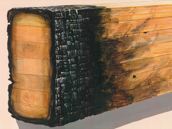
Figure 1: The evaluation of a glued laminated timber or other structural composite lumber will require considerations of factors beyond those discussed in this article.
Case Study
In the example case, the initial available information is as follows:
- Timber floor beams appear to be nominal 12×16 surfaced 4-sides southern pine.
- The client believes the typical char depth is about ½-inch.
- No evidence exists that the timbers were graded.
Often, in older buildings, timbers are not “grade marked” and there are no records of any grading of timbers at time of construction.
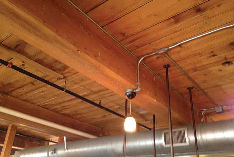
Figure 2: Large timber ceiling beam in renovated 1850 textile mill.
Recommended Steps for Analysis
What follows is a series of recommended steps for analysis of charred timbers. This approach should allow a registered design professional to determine the adequacy of post-fire timbers to carry structural loads. For example, Figure 2 shows a beam in a renovated textile mill that was constructed in 1850. The timbers are valuable and replacement would be extremely costly in the event of a fire event. Replacement of timbers may not be an economical option, thus an in-depth structural engineering analysis, post-fire timber evaluation, and code-conforming re-design could establish that the timbers could be saved for future use.
Step 1. Feasibility “Paper” Study
First, the registered design professional (RDP) can conduct a feasibility “paper” study to initially determine if the residual cross sections of the charred beams have a reasonable chance of being adequate under current code loads and other loads deemed to be appropriate by the RDP.
- By assuming reference properties listed in the National Design Specification® (NDS®) for Wood Construction for a new No. 2 Southern Pine timber (nominal 5×5 and larger) since this is a common grade used; and,
- By reducing the cross-section based on initial estimates of the char depth. The charred layer is assumed to have no residual strength and stiffness.
Based on the outcome of the paper study, the RDP and client can make a decision to move forward as discussed in the next section, in lieu of replacing the timber outright.
Step 2. Preliminary Investigation of Timbers using a Limited Sample of Char Depths
In this step, calculations are refined by more accurate measurements of the dimensions of the charred beam and consideration of thermal damage to the uncharred wood. In a typical fully developed fire, the base of the visible char layer will reflect a temperature of approximately 550°F. Depending on the intensity and duration of the fire exposure, a zone or layer of wood beneath the char layer experiences some irreversible loss in load capacity. While days of heating at 150°F can have a permanent effect on mechanical properties, the temperature effect on mechanical properties is reversible for heating periods of hours at temperatures below 212°F. From temperatures of 390°F to 570°F, the wood components of hemicelluloses and lignin begin to undergo significant degradation. Significant depolymerization of the cellulose component of wood occurs between 550°F and 660°F. Thus, the zone beneath the char layer between 212°F and 550°F has the potential of irreversible loss in mechanical properties due to thermal degradation.
Effects of elevated temperatures are primarily on the strength properties. The effect on stiffness is considerably smaller. In addition to temperature, adverse effects depend on duration and type of exposure. In contrast to the impact on strength properties of wood at elevated temperatures, the loss in tensile strength after cooling to room temperature is greater than the loss in compressive strength.
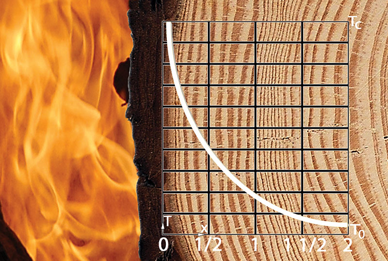
Figure 3: Illustration of temperature gradient in fire-exposed wood member.
Since wood is an insulator, the temperature gradient in the cross-section is typically fairly steep during a fully developed fire (Figure 3). In heavy timbers subjected to fire exposure of the standard fire resistance test (ASTM E119), the 212°F temperature location (or front) will be approximately 0.5 inch inward from the base of the char layer after the first 15 or 20 minutes of fire exposure. In an actual fire, the temperature profile within the wood section will depend on the severity and duration of the fire exposure and post-fire exposure. One can account for additional thermal damage to uncharred wood in the load capacity calculations by including a zero-strength layer in the dimensions of the residual cross section (Figure 4).
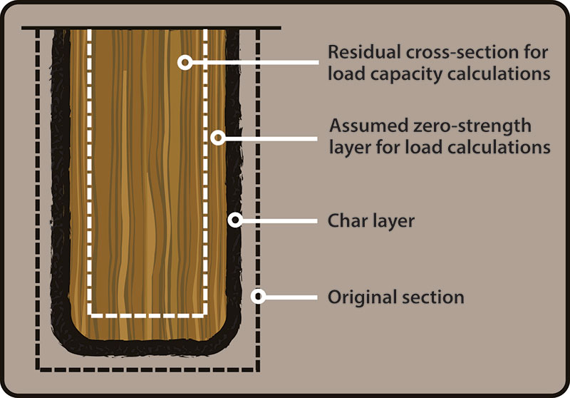
Figure 4: Illustration of zero-strength layer model of fire-damaged wood beam.
In Evaluation, Maintenance and Upgrading of Wood Structures, A Guide and Commentary published by the American Society of Civil Engineers (ASCE) in 1982, recommendations for evaluation of fire damage were for “removal” of a fixed amount of wood. Recommendations included removal of the char layer plus approximately ¼ inch or less of wood below the base of the char layer. For members controlled by compressive strength or stiffness, the recommendation was that no additional adjustment beyond removal of ¼ inch was necessary to apply the basic allowable design stresses to the residual cross-sectional area. For members controlled by bending strength or stiffness, the recommendation was either removal of an additional 0.625 inch or removal of an additional ¼ inch in combination with a 10% reduction in the allowable design value used to calculate the load capacity of the residual cross-sectional area.
The code accepted methodology for calculating fire resistance ratings for heavy timber members addresses the anticipated thermal degrade effect on load capacity in the fire test by assuming an additional equivalent thickness having no strength and stiffness, and by using “room temperature” published properties for the residual cross sectional area. The analysis assumption is that “damaged” wood provides an “equivalent” thickness of load capacity. In the fire resistance calculation methodology in the NDS (Chapter 16), the equivalent thickness for the heated and thus potentially damaged section is 20% of the calculated char depth. Using the normal assumption of a char rate of 1.5 inches per hour, the 20% calculation for the zero-strength layer is equal to 0.3 inch for a one-hour fire resistance rating. This 1.2 factor adjusts the thickness to reflect the fire duration and its likely impact on thermal penetration into the wood interior. The methodology has been shown to be applicable to both dimension lumber members as well as heavy timber members.
It is likely that a post-fire temperature profile will be flatter and of longer duration than the standard fire resistance test profile. Longer duration of elevated temperature in the interior portion of the member may increase the permanent loss in strength. The total duration includes both the fire and the post-fire period of elevated internal temperatures. The temperature at the char layer base should quickly be considerably less once the fire is extinguished, and thus reduce the thickness of wood subjected to the more severe elevated temperatures.
In applying the methodology to the available strength data for permanent strength loss and the temperature profile reported for ASTM E119 fire exposure for various durations, the authors concluded that 0.1 inch to 0.3 inch is a reasonable recommendation for the zero-strength layer of a member loaded in compression in a post-fire load capacity analysis when used with the NDS adjusted design values. For members loaded in tension or bending, the recommendations are a thickness of 0.3 inch to 0.5 inch. These recommendations assume that the zero-strength layer is not physically removed from the member and the temperature at the center of the timber did not increase based on the likely temperature profile during the fire. One can further adjust the depth of the zero-strength layer downward by a fraction (e.g. 50%) of any uncharred depth removed for appearance reasons. Selection of values between 0.3 inch and 0.5 inch should be based on the duration of the fire as reflected in the observed char depth and location of members relative to direct exposure to flames. The observed thickness of the residual char layer will be less than the observed reduction in the dimensions of the charred member due to shrinkage of the char layer. In the context of these recommendations, 0.3 inch for compressive members and 0.5 inch for tension and bending members are the more conservative values for the thickness of the zero-strength layer in the calculation of load capacity.
In continuation of the example,
- The RDP obtains measurements of the char free cross section. In this example, measurements indicated the residual width B’ of the beam was 10.6 inches and residual height D’ was 14.6 inches.
- Available information on the fire indicated the beam was directly exposed to flames and that the fire was extinguished shortly after flashover. The intense short-duration fire produced about ½ inch char, but thermal penetration into uncharred wood was likely limited. Thus, the conclusion in this example is that the additional reduction via a zero-strength layer of 0.3 inch is appropriate for calculation of residual load capacity.
- To estimate the effective post-fire B and D dimensions.
B* = effective post-fire width = B’ – 2(0.3) = 10.6 – 2(0.3) = 10.0 inches
D*= effective post-fire depth = D’ – (0.3) = 14.6 – 0.3 = 14.3 inches
With Step 2 completed, the RDP has the basic information (B* and D* estimates) needed to conduct a preliminary structural analysis with respect to adequacy of the example fire-exposed timber floor beams. This preliminary structural analysis is conducted using the NDS adjusted design values for the grade/species as installed (if known) or new No. 2 Southern Pine timber. If the results are favorable with respect to demonstrating code compliance, a decision can be made by the RDP and client to further process the timbers to reduce them to their final dimensions and establish the grade and species of the beam whereby the structural design properties of the processed timbers will be available for use by the RDP.
Step 3. Documenting the Species, Grade, and Size of Each Timber
In this step, add the potential impact that the reduced cross section had on the structural grade of the timbers.
- This step is necessary because visual stress grading rules are based on member size and characteristics (such as knots) of the outer zones of a member that greatly impact stress grade results.
With the timbers “clean” and reduced to their final dimensions, the RDP should contact a supervisory grading agency to evaluate all of the affected timbers in the structure. A list of grading agencies is available on the web site of the American Lumber Standard Committee, Inc. The grading agency can make a qualified statement for each timber based on what grade characteristics are evident for each beam. For example, by viewing a beam in-situ, the grading agency can conclude that the highest possible grade for the specific beam is No. 2 because the beam exhibits characteristics that exclude it from the No. 1 grade. Knowing the most optimistic grade for each beam, the RDP would be required to make the necessary judgments on a reasonable “design” value to use in the engineering process. The maximum potential grade for each beam should be established and documented by the engaged supervisory grading agency. Also, the RDP should measure and record the residual size of each timber for use when checking all fire-exposed timbers in the structure. The final sizes may be different from the sizes calculated under Step 2.
With Step 3 completed (the timber species or species group identified, visual stress rated grades confirmed, and section dimensions recorded for each timber), the RDP has an available set of visual stress rated design values for each timber to use with the effective post-fire section B* and D* dimensions. The RDP should also verify that the timbers are “sound” and have not been damaged by factors other than fire exposure.
Additional Considerations
- Since the timbers have been in-service, they may be decayed and thus timbers should be thoroughly inspected for presence of decay.
- Decay in a structural timber trumps all other factors that impact strength and stiffness, and therefore, a decayed timber cannot be relied upon to support in-service loads.
- The load history of the timbers may be important. The possibility of overloads in-service, or cumulative damage, should be investigated.
- The authors limited the scope of this article to solid sawn timbers. Laminations of different grades are often used in construction of a glued laminated timber. Th e inability to view the wide faces of the interior laminations will complicate the necessary re-grading of the residual beam. In addition, glued laminated timbers use very high quality outer tension laminations and the loss of these tension laminations due to a fire can severely impact the possibility of salvaging these timbers.
Conclusion
Structural evaluation of an existing wood structure, even without fire exposure, is an order of magnitude more difficult than the design of a new structure with new materials. In addition to collecting basic input information for structural analyses (species, timber sections, timber grades, timber condition, etc.), structural design experience is valuable as engineering judgment is likely to be needed in each specific case.▪