
The term “sliver building,” according to the New York City (NYC) zoning code, is specifically reserved for a tall building or enlargement that is 45 feet wide or less. In many cases, such buildings are restricted to a height equal to the width of the abutting street or 100 feet, whichever is less. However, when considering the structural stability of a building, a “sliver building” is commonly a narrow building having a large aspect ratio (height to width). Even though a building may not specifically be designated as a sliver building according to the local zoning code and building department, engineers often encounter similar conditions which often present stability issues due to the narrow width when resisting lateral loads.
The following example is mixed-use and located in the heart of New York City on East 61st Street. It features three floors of commercial space with a restaurant and salon, and three residential floors with a penthouse above. The six-story building with penthouse, basement and cellar has effectively seven levels above grade and one below grade. The width of the building is only 19 feet, and the depth extends 90 feet – almost the entire length of the property. The height-to-width aspect ratio, with respect to grade, is 3.45 (Figure 1).
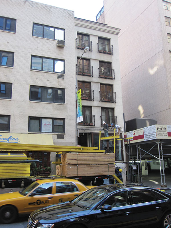
Figure 1: Building before renovation.
Major architectural modifications required the building to receive a new limestone and expansive glass wall façade, extending it horizontally 7 feet toward the street. Each floor of the building was therefore extended as well (Figure 2).
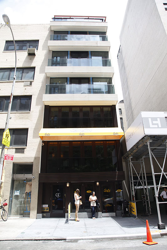
Figure 2: A view of the completed building renovation.
The construction of the building is circa 1910. During its life it received various modernizing alterations as well as alterations to accommodate new tenant uses, prior to the enlargements discussed here. The original timber floors, which span between the west party-wall and the exterior east property line wall, have been reframed with cold-formed C-joists and concrete deck to accommodate a change in floor heights and architectural layouts requiring new penetrations for an altered stair location and the addition of an elevator. The wall construction of the building is brick masonry supported on rubble foundations. Portions of the rubble foundation and brick masonry walls have been extended, by underpinning methods, to enlarge the cellar level.
The building was originally designed to utilize the perimeter masonry as shear walls to provide the lateral load resistance in both directions. The original engineering of the walls was an empirical design similar to that specified in the 1938 NYC building code. Wind loads are presented in the historical design code, but earthquake loads were not considered at that time. The building’s lateral load resisting system had to be altered due to the removal and replacement of the entire front facade. To alter the existing building’s structural system, several issues existed: (1) determining which of the permitted building codes, old (1968) or new (2008), should govern the proposed structural modifications; (2) choosing the appropriate structural design criteria; and (3) deciding how to engineer and construct the building’s new lateral load path.
The 2008 NYC Building Code (2008 NYCBC), a modified version of the 2006 International Building Code (IBC), is the current governing design standard. The design wind load is 20 psf and the seismic response coefficient is 0.088 for this building, with site class B and a response modification factor of 1.0. The 2008 NYCBC called for a seismic upgrade of the entire building, including the unreinforced brick walls and diaphragm connection details. This would have required a huge amount of structural work and added considerable cost for this old building’s renovation.
In order to balance the necessary scope of a seismic upgrade with a reasonable renovation cost, the 1968 NYCBC is permitted as an alternative design option. It presents almost the same design wind loads as the 2008 NYCBC, but an entirely different earthquake load which is in accordance with 1988 Unified Building Code (UBC) with certain exemptions and reductions. The renovation would add 1,660 square feet to the original 10,800-square-foot building. The combined 12,460-square-foot building has seismic forces (base shear and overturning moment) 15.4% greater than the forces in the original structure. As the increase in forces is less than 20%, the enlargement renovation is considered “small” per the 1968 NYCBC. Therefore, although the earthquake load analysis is still required for the new construction, the seismic upgrade of the existing building is not. The equivalent seismic response coefficient for the enlargement is 0.049, smaller than indicated by the 2008 NYCBC. Based on these studies, the final lateral system analysis of the new construction used a seismic response coefficient of 0.088 in accordance with the 2008 NYCBC (Figure 3).
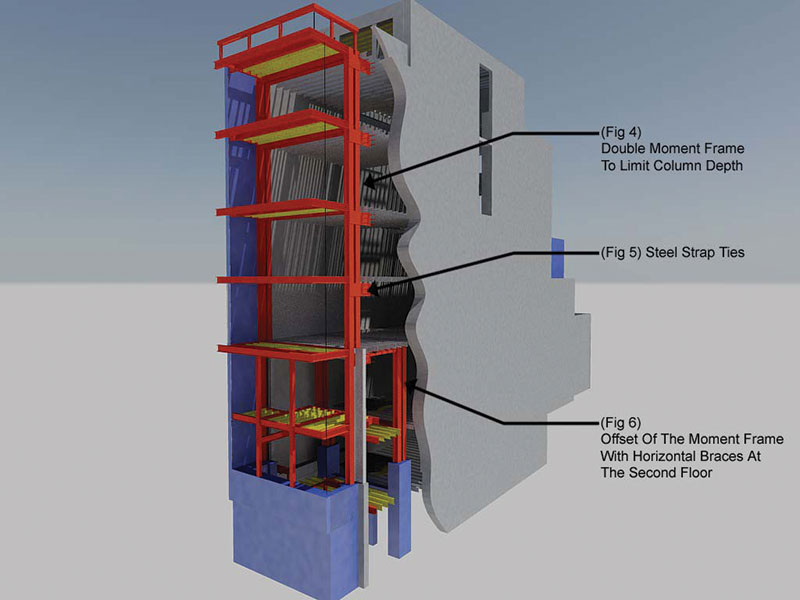
Figure 3: 3D rendering of the building renovation structural system.
Rigidity of the floor diaphragm is an important factor in the lateral load analysis. If the average deformation of the floor diaphragm is less than or equal to two times the story drift, it can be considered rigid and the diaphragm shear forces will be distributed based on the rigidity and location of the lateral-load-resisting systems. According to ASCE 7-05, concrete filled metal deck diaphragms, with an aspect ratio (diaphragm span to width) of 3 or less, can be considered rigid. When the aspect ratio is larger, the diaphragm is considered flexible and the diaphragm shear forces will be distributed based on the tributary area of each lateral-load-resisting system only. Another option is to treat the diaphragm as semi-rigid and conduct a load effect envelope analysis with both rigid and flexible assumptions. As the building in this case has a floor diaphragm aspect ratio of 4.5 at the lower two floors and 3.25 at other floors, assuming a flexible diaphragm simplified the lateral force analysis.
As a result, a new lateral-force-resisting system had to be installed after the front wall was removed to maintain two such systems in each direction. A braced frame would be the most efficient, but not desirable from an architectural perspective. In order to leave the entire space open, a moment frame system would be the only solution. The moment frame had to be designed using the same response reduction factor (i.e., 1.0) as the existing unreinforced brick wall in the earthquake load calculation per the 2008 NYCBC, representing the total elastic forces generated by the expected seismic event.
It also needed to have considerable stiffness, not just adequate strength. The limitation on the building’s exterior wall deflection is 0.0083 (1/120) times the wall height in the 2008 NYCBC under wind load effects. The allowable seismic story drift is 0.01 times the story height for the cantilevered masonry building. This criterion is adequate if there are no adjacent buildings; otherwise, it is required to create a structural separation of 1 inch for every 50 feet in height, equivalent to 0.0017 times the building height. A 1.5-inch separation was established for this building at the top, per the code. The preliminary design indicated that the moment columns had to be 18 inches deep to meet the deflection requirements. The architect of record required reducing the column depth to create more space, resulting in a double moment frame system that increased the clear space by 16 inches within the frame plane (Figure 4).
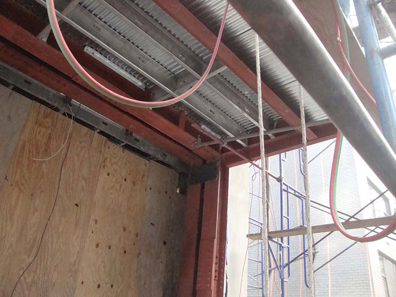
Figure 4: Double moment frames.
The moment frame is connected to the metal floor deck by puddle welds for diaphragm shear force transfer at each floor. Being long and narrow with a large aspect ratio in plan, the floor diaphragm might exhibit so-called bow actions, which would subject the wall to torsional deformation and stresses at the ends. To resist the possible bow actions, steel straps welded to the moment frame were bolted into the brick walls to create sufficient bond to the side walls (Figure 5). The moment frame was discontinued at the second floor level due to the moment beam interfering with the front stair opening. The columns extend to the basement, and a new double moment frame system was installed 10.5 feet behind the front ones, from the second floor down to the basement. To transfer the shear forces securely, horizontal braces were designed at the second floor in between these two moment frames (Figure 6). The steel moment frame ended at the basement on a concrete shear wall, which safely dissipates the lateral forces into the ground.
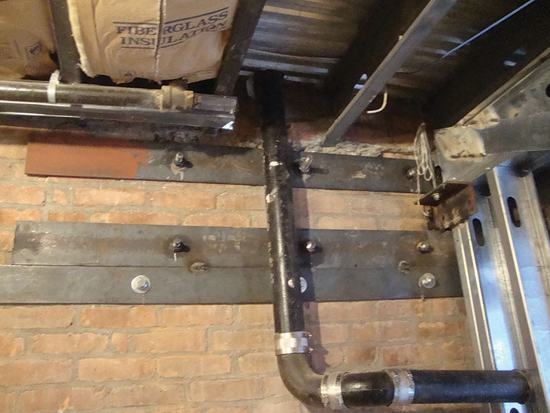
Figure 5: Steel strap ties on wall.
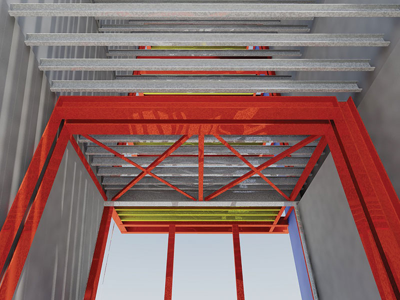
Figure 6: Offset of moment frames at second floor.
Renovation of this kind of “sliver building” for adaptive reuse is typical and popular in NYC. Whenever there is an increase of openings in a wall, or even total elimination of the wall, the first question facing an engineer is whether it is necessary, and how to design a new lateral-force-resisting system in accordance with the governing building code, especially in regard to the need for a seismic upgrade. It is not only a pure structural problem, but also an economic concern for the property owners. The 1968 NYCBC presents conditions for different extents of building renovation design, which could lead to a new model building code for existing buildings.▪