
As a part of Pennoni’s on-call contract with an existing client, the Philadelphia structural division investigated and developed repair bid documents for an existing, three-level, 1,200-space precast concrete parking garage during the last quarter of 2012. Part 1 of this series (September 2013) described the existing structure and summarized observations and material testing results. This article presents an analysis of those findings.
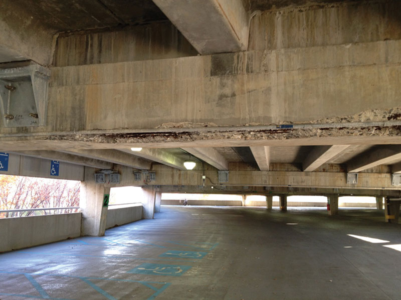
Figure 2: Spalling due to deteriorated strands at precast girder.
Observations
The surface spalling and subsurface delamination observed at the girders occurred due to the corrosion of the internal reinforcing (Figures 2 and 3 from Part 1). Corrosion is an electrochemical process that requires an anode, a cathode and an electrolyte. For the existing structure, the moist concrete provided the electrolyte and the embedded reinforcement provided the anode and cathode. Water and oxygen must be present for any corrosion to take place and, in good-quality concrete, high alkalinity slows or stops the corrosion process. However, if the concrete alkalinity is lowered (e.g., due to carbonization) or if corrosive chemicals (e.g., chlorides) are present, the corrosion process will accelerate.
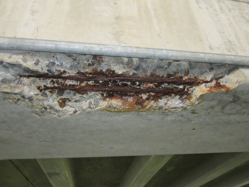
Figure 3: Corroded and failed prestressing strands at precast girder.
The electrical current that flows between the cathode and anode results in an increase in metallic volume at the anode as iron is oxidized and precipitates as rust. Rust, a byproduct of electrochemical reaction, has a volume three to four times greater than the iron anode from which it originates. As the layer of rust increases due to the ongoing corrosion process, the resulting expansion of the corrosion byproduct causes the surrounding concrete to crack, delaminate and ultimately spall. As the surface of the concrete degrades, the corrosion process accelerates as internal areas of the reinforcing that were previously protected by the concrete cover are exposed to additional moisture and deicing salts (chlorides).
The decrease in frequency of deterioration at the second floor girders was likely because fewer deicing salts were used, since this floor was not directly exposed to snowfall. The post-tensioning cables, whether ducted and grouted or sheathed and unbonded, were somewhat protected from the high chloride content and as a result did not corrode as extensively as the unprotected prestressing cables at the precast girders. The mild reinforcing at the post-tensioned girders was not protected from direct contact with the surrounding concrete, and would therefore be expected to deteriorate over time.
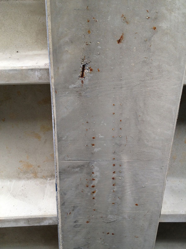
Figure 4: Rust staining due to internal corrosion of post-tensioned girder reinforcing.
However, field observations (Figure 4 from Part 1) indicated a general lack of spalls and subsurface delaminations in the post-tensioned girders. It was also noted that the cast-in-place, post-tensioned girders were constructed at a slightly later date than the precast girders, so the embedded reinforcing may not have created enough corrosive byproduct at the time of the condition assessment to create spalls as frequently as was observed at the precast prestressed girders.
Material Testing
Water Soluble Chloride Content
In order to prevent the corrosion of internal reinforcing steel and the subsequent deterioration of the surrounding concrete, the American Concrete Institute (ACI) recommends that the initial ratio of water soluble chlorides to weight of cement not exceed 0.06% for prestressed structures in a moist environment that are exposed to chlorides in either the form of admixtures or deicing salts. The chloride powder sample tests indicated that the actual chloride content was as high as 25 times greater than this recommended limit (Table, sample PAI-1). Some of the chloride content in the samples taken from the top surface of the concrete likely resulted from direct exposure to deicing salts (Table, samples PAI-4A and 5A). However, the magnitude of the chloride content at the beams suggested that there was a secondary source of chlorides in the concrete.

The most likely explanation is that a set-accelerating admixture containing chlorides was used in the original concrete mix. This hypothesis was based on the following rationale:
- Set-accelerating admixtures are typically only employed during winter concreting operations when there is a desire for the concrete to set more quickly than normal in order to avoid freezing of the mix water before complete hydration occurs. A review of the available construction phase documentation indicated that the cast-in-place post-tensioned girders might have been placed during cold weather. In precast operations, when there is a desire to accelerate fabrication and reduce turnaround time associated with the curing of the concrete, set accelerators are also employed.
- A comparison of the latest powder samples from the third level precast girders with one taken from a second level precast girder indicated a greater concentration of chlorides at the third level. As indicated previously, it is reasonable to assume that the girders on the second level had not been exposed to large quantities of deicing salts, so the measured chloride content should have been about the same as the initial chloride content when all of the beams were cast. It is also reasonable to assume that the 2-inch cast-in-place topping slab did not contain chloride set accelerators, based on previous material testing, and likely had an initial chloride content of approximately 0%.
- Assuming that the initial chloride content was 0.97%, a comparison of PAI-2 (third floor girder) to PAI-6 (second floor girder) indicates a 0.075% chloride growth over the past 20 years. If the topping slab did not initially contain chlorides at all, then the chloride growth in sample PAI-5A (topping slab) of 0.07%, is approximately the same amount as would be expected over the same time. A similar separate comparison of PAI-1 (third floor girder) to PAI-6 (second floor girder) indicates a 0.545% chloride growth over the past 20 years. The chloride growth in sample PAI-4A (topping slab) is 0.595%, which is also approximately the same.
- The previous chloride tests performed as a part of earlier reports of investigation also allow for the chloride growth rate to be compared and verified to the latest results (see Table). As previously indicated, the estimated chloride growth in the girder for sample PAI-2 is 0.07% over a 20-year time span. This equates to a 0.0035% growth rate per year. The previous 2002 sample D-2 indicates a similar chloride content growth of 0.003% per year over a ten-year span, while the 2005 sample 3t indicates an identical growth of 0.0035% per year over a 13-year span.
By verifying the chloride growth rates as shown in the analysis presented above, it is reasonable to conclude that chloride-containing set accelerators were used in the original precast, prestressed and subsequent post-tensioned girder construction. This appears to be the most rational explanation for the extremely high chloride content in the girders discovered by the material testing.
It should be noted that none of the previous testing performed in 2002 or 2005 included chloride testing from the girders. As a result, Pennoni compared the old and new chloride content test results from the topping slabs to extrapolate and confirm the likely chloride ion growth in the level three girders. In addition, the testing performed at the girders allowed for the identification of the primary cause of the rapid deterioration of the same members, which was not included in the previous investigations.
Petrographic
With the exception of the deleterious conditions identified by the material testing described above, the results of the petrographic analysis of the six core samples indicated that the concrete appeared to be of good quality. However, either the concrete was not air entrained, or an insufficient amount of air entrainment admixture was used, resulting in diminished protection of the concrete against freeze-thaw damage.
Concrete normally exhibits entrapped air of approximately 3%. Per Table 4.4.1 in ACI 318-08, the concrete used to construct the exposed slabs and girders of the garage should have had an air entrainment of approximately 6%. Chemical admixtures are typically introduced into the wet concrete mix to increase the air entrainment to 6%, thus greatly increasing the protection against freeze-thaw damage. The additional air voids allow for moisture to expand as it freezes, thereby reducing the internal stress on the concrete.
In addition, the large quantity of water voids in the six core samples indicates that additional water was added to the wet concrete mix after the initial batch was prepared. This construction practice normally occurs to increase the workability of the wet concrete (increase slump) for placement. The increased workability comes at the cost of strength and durability, since the water/cement ratio is increased. However, the compressive test results from the previous 2002 report of investigation indicated that the concrete achieved the desired compressive strength.
Carbonization
Concrete is highly alkaline (i.e. high pH) due to the presence of calcium hydroxide created during the cement hydration process. The high alkalinity of concrete protects internal reinforcing from corrosion by creating a layer of passivity around the embedded steel. When concrete is exposed to carbon dioxide from the combustion exhaust of vehicles and the surrounding polluted atmosphere, the gases are absorbed by the concrete and react with dissolved calcium hydroxide associated with the free moisture located in the pores of the concrete. As a result of this reaction, the alkalinity of the concrete is reduced from its normal pH level of approximately 12.5. Once the pH level reaches approximately 9, the layer of passivity is lost and the internal steel is no longer protected from corrosion.
The results of the carbonization tests at all six cores indicated that only the exposed concrete surfaces, to a depth of no more than 0.6-inch (see Table, core sample PAI-2) had been carbonized. The typical clear cover established by field observations was ¾-inch, so the presence of the carbonated concrete is not currently contributing to the direct loss of corrosion resistance of the internal steel.
Practical experience has demonstrated that the depth of carbonization normally increases 1 inch every 50 years, or 0.02 inches per year. This value is confirmed by noting that the 2002 material testing indicated a depth of carbonization of approximately 0.5-inch. Based on the 0.02-inch per year estimated growth rate and the 7-year elapsed time period between measurements, the depth of carbonization should be approximately equal to 0.64-inch.
Service Life Analysis
By extrapolating from the carbonization analysis, the depth of carbonization will reach the embedded reinforcing in approximately two to three years. Once the carbonization reaches the internal reinforcing and the passivity layer is lost, the reinforcing will begin to deteriorate at an accelerated rate, greatly reducing the expected future service life.
In addition, Pennoni used ACI 365.1R-00, Service Life Prediction – State of the Art Report, to evaluate the remaining service life of the garage due to the high chloride content of the precast girders exhibited by samples PAI-1 and PAI-6. The criterion provided in this document essentially evaluates the time required for the embedded reinforcing to create a delamination and spall based on the clear cover, chloride content and reinforcing size. At the time a spall is created per the calculation, the service life of the member is essentially over, because repairs will be required for both the spall and the corroded reinforcing.
The results of the calculations indicated that the precast concrete girder at the third floor represented by sample PAI-1 had a remaining service life of approximately two years, while the girder at the second floor represented by sample PAI-6 had a remaining service life of approximately four years.
Parts 3 and 4 of this article will appear in future issues and discuss conclusions and recommendations for the temporary repair, stabilization and ultimate replacement of the garage.▪