
During site work and, specifically, underpinning work involving existing buildings, it is best practice to perform monitoring of any buildings in the vicinity that may be influenced by the work. This monitoring includes both optically surveying the existing structures for displacement and installing vibration monitors to continuously monitor and record peak particle velocities. Both movement and particle velocity data can be used as tools to alert the monitoring engineer of potentially damaging site conditions or construction practices, and to provide valuable time necessary to prevent or mitigate damage due to the construction work. Excavation beneath or adjacent to foundations and use of vibratory equipment can have drastic impacts to soils beneath existing buildings.
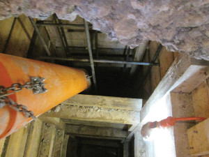
Figure 1. Installing an underpin beneath foundation.
The New York City Building Code, Section 1814.3, requires this monitoring during any underpinning activities (Figure 1). Monitoring is also required during any site work within ninety feet of a Landmarked Building, a designation specified by the NYC Landmarks Preservation Commission (LPC). Technical Policy & Procedure Notice 10 of 1988 (TPPN 10/88) specifically outlines these requirements. The requirement applies specifically to landmarked buildings because they are particularly susceptible to damage. This is due to several factors.
Landmarked buildings can be structurally deficient due to their age. Many landmarked buildings that this author has reviewed were originally constructed as shared-party-wall buildings and, through decades of renovations, often no longer possess robust lateral systems. Adjacent building demolition and the associated removal of floor diaphragms that brace these party walls, coupled with the subsequent partial undermining of these walls during underpinning processes, can cause subsidence and out-of-plane movement.
Often, monitored landmarked buildings possess rubble foundations. These foundations are comprised of medium-sized boulders. The material may have been assembled with or without mortar or grout. If used, often times the mortar has significantly deteriorated. The pieces of rubble perform poorly as pits are excavated beneath them for the underpin installation; they do not bridge over these pits as well as newer reinforced concrete foundations. Larger boulders typically perform better than smaller to bridge over these excavations. Monitoring performed by the author in these instances has revealed that when performing this excavation for installation of underpinning pits, local subsidence can occur, even with the commonly-specified excavation width of four feet per pin. Three feet is now often specified due to these observations. Optical monitoring in these instances is most useful and can reveal most vertical and out-of-plane displacements. Collection and review of the monitoring data helps the engineer evaluate the performance of the specified construction in real-time and react accordingly, possibly by specifying additional bracing and shoring prior to continuation of underpin installation and/or reducing the number and size of pin pits that may be open simultaneously.
Soil types can also impact how a building performs and reacts during construction work. When installing piles or removing rock, vibratory equipment can cause sandy soils to settle or spill out into inadequately-supported excavations. Vibration monitoring can provide forewarning of such events and help to proactively address potential undermining due to excessive vibratory loading.
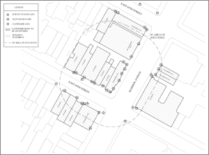
Figure 2. Monitoring plan diagram with 90 foot radius indicated.
The LPC requires monitoring of all landmarked buildings within 90 feet and in all directions of the work being performed (Figure 2). While this radius may seem excessive based on an average depth of excavation, say 20 feet, and an average angle of soil repose of 45°, the 90 foot radius also takes into account the potential for vibratory equipment to affect soils under buildings at this distance as a vibration wave propagates outward. While direct effects of soil removal are not anticipated at a 90 foot distance, sandy soils can settle during pile-driving or rock blasting, and effects of these vibration loads can be observed at this distance.
A building’s structural monitoring program is comprised of three components: optical monitoring, vibration/movement monitors, and telltale crack gauges.
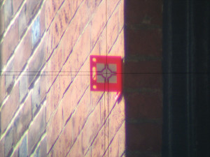
Figure 3. Collimation of a target through a total station.
Optical monitoring consists of the installation of targets on the façade (Figure 3) of each building to be monitored. Typically, targets are installed at a height equal to the 2nd floor or 3rd floor framing and spaced along the façade every five to ten feet horizontally. The first signs of any settlement are easily observable in the data when arranging targets in this orientation. This is because placement in the lower floors allows for any localized settlement to be observed. Separation and cracking can occur above due to arching and other factors. This can result in little movement in the upper portions of the façade being measured, skewing results. The placement also allows the targets to be maintained out of reach of pedestrians and above potential obstacles such as vehicles. The sighting of targets is performed from the sidewalk level, and located at a set station mark, typically on a sidewalk.
Targets may also be placed in a grid over portions of, or the entire façade to monitor for potential out-of-plane movement. This technique can be utilized if the building’s exterior wall is suspected of being inadequately connected to its floor diaphragm. This may occur in the case of a party-wall building where the contiguous building has just been demolished to make way for new construction. The remaining building could potentially possess large unbraced lengths of wall due to a stair or other shaft extending the height of the building.
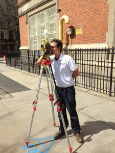
Figure 4. Surveying of monitoring points.
Optical monitoring is performed with a total station (Figure 4) and typically occurs multiple times per week. The frequency is increased if the monitored structure is deemed particularly vulnerable or if any movement trends are observed. During data collection, reference points are recorded in the form of previously-set benchmark target locations. The recorded monitoring data is compared to these benchmark locations to calculate any displacements that have occurred in three directions – the in-plane lateral (sideways) direction, out-of-plane lateral direction, and vertical (Z) direction. The directions are not always described in the same fashion as typical surveying coordinates, i.e. as Northing and Easting, because the direction relative to the face of the material being monitored is of primary concern.
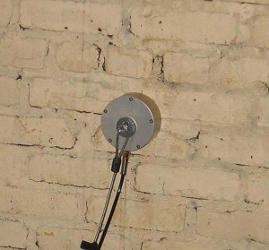
Figure 7. Attachment of a vibration monitor geophone.
The vibration monitoring equipment, commonly utilized to collect seismic data and blast activity monitoring during mining, consists of a tri-axial geophone (Figure 7) to convert movement into an electrical signal. The signal is then recorded and, when coupled with a modem or internet-connected hardware, can be uploaded to the monitoring engineer’s server for real-time data review and immediate event alerts. The vibration monitors are placed on all adjacent and contiguous foundations surrounding the project site. A microphone can also be incorporated into these systems, which allows for the recording and monitoring of decibel level caused by the construction.
The third component in the monitoring program is a gauge that is applied across existing cracks and other deficiencies. These crack gauges consist of two plates that are attached on either side of the separation. One clear plate crosshairs overlaps the other plate which contains graduations. If the two sides of the separation shift relative to each other, the crosshair plate shifts compared to the graduated plate and this shift can be read by the crosshair end locations. These gauges are regularly observed, and separations are documented and reported in conjunction with optical and vibration data.
Monitoring criteria varies between industries, jurisdictions, and the composition of the building being monitored. The established criteria in NYC are specified in TPPN 10/88. The criteria specify a threshold of ¼ inch of movement displacement, and ½ inch/sec velocity limits. The monitoring plan must detail the procedure if these limits are exceeded. The engineer of record and the Department of Buildings are typically alerted as part of this procedure. The technical bulletin is largely based on the conclusions of a 1981 ASCE article regarding a case study of monitoring in a Historic District in downtown NYC during adjacent excavation. The conclusions of the article discuss the success in monitoring results reflecting measurable damage based on the peak particle velocity and movement criteria along with monitoring frequency utilized in the program.
The ideal result of monitoring, of course, is that no significant movement or vibration occurs and therefore none is detected. A carefully prepared underpinning and Support of Excavation (SOE) design, along with an experienced, competent contractor can often result in an uneventful monitoring report. Proper due diligence must be performed. This includes the review of soil boring logs and collecting and documenting the existing condition of neighboring buildings. Any pre-existing conditions must be addressed before the contractor commences. This can be very difficult with adjacent occupied buildings or unfriendly, litigious neighbors. Some sites are difficult because of the site conditions themselves. Soil bearing capacity may be low, or inadequate existing foundations are present. When adverse site conditions are present, techniques such as jacking and shortening of pin pit widths should be considered. A thorough monitoring plan is critical in every instance. The monitoring protects the owner, and provides a forewarning before common damages such as interior wall finish separation and brick masonry mortar joint separation are observed.
Case Study
In one particular instance, multiple brownstones are proposed to be renovated simultaneously in order to be combined into a single new building. The brownstones are landmarked and their façades must be preserved. One of the lots is on a corner, with a long wall of the brownstone facing the street, unbraced by any other building. New floors are proposed to extend beneath the existing foundation, and underpinning is necessary. A difficult situation arises. In this case, the corner building is braced with temporary horizontal steel that is extended through the neighboring buildings to be demolished and into the next building’s bearing wall, which is to remain. Bracing could have instead extended downward into the ground, but the temporary structure would have then caused coordination issues when installation of the new structure moves forward.
Timber floor framing and floor decking in the pre-existing corner building are deficient. Efforts were made, prior to underpinning, to better connect the floor diaphragm at each floor into the load-bearing masonry walls. Floor framing was re-decked where appropriate, and all connections into the exterior façade, the front and rear walls, and the party wall were bolstered. In demolishing the adjacent building at the shared party wall, a long, slender building results.
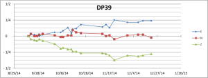
Figure 5. Graph of the displacement of a monitoring point.
The next stage, underpinning of the rubble foundation, then proceeds in sequenced excavations. Excavation width is limited to four feet, pin width is limited to three feet, and all efforts are made to minimize the disturbance of existing soils. Unfortunately, lateral movement and vertical settlement approaching the ¼ inch limit are observed during the underpinning process (Figure 5). As a result, work is stopped and additional bracing and steel reinforcement is designed by the engineer to bolster the frame of the building. Additional targets are applied to the exterior face of the building in order to record a more precise profile (Figure 6) and monitoring frequency is increased to a 48 hour schedule. The additional shoring is developed to essentially create a temporary steel diaphragm, “grab” the existing masonry façade, and connect it directly to the horizontal steel bracing attached to the adjacent building. This effectively arrests all movement and the contractor is able to proceed with underpinning, completing it without further movement.

Figure 6. Typical target on landmarked building.
Overall, an inadequate lateral system combined with subsidence of the soil during pin excavation to cause slight vertical settlement. This in turn caused out-of-plane movement of the wall. While the building was originally constructed as free-standing prior to construction of its adjacent building, excessive renovation eventually caused it to rely on its contiguous neighbor. Even after reconnection of existing diaphragms and horizontal bracing extending to farther neighboring buildings, the removal of the contiguous building combined with the excavation performed beneath the foundation for underpinning caused slight movement. Monitoring of the building alerted the engineer to the condition, and the design and installation of an additional temporary structure arrested this movement.
It is important to consider all aspects in the preparation of each monitoring plan. A thorough understanding of existing soil conditions, structural conditions, along with the proposed scope of site work will help to develop an effective plan. Close coordination with the structural engineer, general contractor, and architect will help ensure a safe process that runs smoothly to address any building movement that may occur during construction.▪