The First Precast Open Box Girders for Phoenix and Arizona
This is the second in a series of articles about the components of the new PHX Sky Train™ in Phoenix, Arizona. Part 1 of the series was published in the July 2013 issue of STRUCTURE magazine, and Part 3 will appear in an upcoming issue.
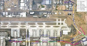
The initial 2-mile stage of the nearly 5-mile long PHX Sky Train™ opened on April 8th, 2013. The Sky Train is a planned automated transit system that will link the terminals of Phoenix Sky Harbor International Airport (PSHIA) and the economy parking lots at the east and west end of the airport with the consolidated rental car facility and the valley’s Light Rail system. The system provides a fast, safe, convenient, and more sustainable transportation link that will serve an expected 2.5 million passengers a year and provide the springboard for future growth.
Currently operating, Stage 1 is approximately 2 miles long, with over 1.5 miles elevated, including three stations. Stage 1A, which is under construction, is expected to become operational in early 2015, and extends the system by another ¾ mile to a fourth station. The elevated guideways comprise a variety of structure types, from steel girders to cast-in-place post-tensioned box girders to precast prestressed concrete girders. This mix was dictated primarily by constructability and cost considerations. The Airport elected to execute this project through a Construction-Manager-At-Risk (CMAR) who was selected early in the design process and provided crucial input to the facilities design team regarding optimum choices for different sections of the system. The precast open-box girders for a majority of the elevated guideway is one of the most visible examples of a design choice influenced by the input received from the CMAR. This article discusses the process behind selection and evolution of the open-box girder used in the guideway.
From Cast-In-Place to Precast
Cast-in-place (CIP) post-tensioned box girders are a common and popular choice for bridges in Phoenix and across Arizona, and were a natural initial choice for the elevated guideway. The CIP box girder is well suited to the curved alignment of the train and the typical span lengths under consideration, and all local contractors are experienced in construction procedures. This structure type was chosen in the 30% design documents used in selection of the CMAR.
The CMAR suggested that precast concrete girders might be better suited to construction within the airport, with advantages in cost, time of construction and reduced congestion due to elimination of falsework and cited the success of a precast girder system in a similar airport train system they had recently completed. They brought this suggested change to both the designer and owner for further discussions. The owner liked the potential cost and time savings, but preferred the clean shape of the CIP box girder to the more angular appearance of the standard precast I-girder alternative typically used in Arizona. The CMAR’s previous project used a combination of two different shaped precast girders in conjunction. The precast Texas U54 box girder was placed in the more visible location, partially shielding the AASHTO Type IV girder. However, the Texas standard box girder is not used in Arizona, and local precasters had no experience in their construction nor the forms or infrastructure required.

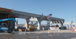
The elevated guideway under construction, showing erection of the U-beams. Courtesy of Gannett Fleming, Inc.
Selecting and Optimizing the Shape
The CMAR facilitated a meeting between the designer and a local precaster to discuss options. The cost of using standard box girders from another state was obviously high. Discussions therefore focused on the advantages and disadvantages of paired girder types versus a system of all AASHTO I-girders, either all Type IVs or Type Vs. The mixed girder type was the most expensive, with additional cost premiums because of the limited quantities of each type of girder. However the project had been approved and presented in numerous public meetings using the trapezoidal box girder shape, and the owner was reluctant to abandon the agreed upon structure in favor of an exclusively I-girder system. Given the general consensus against a mixed girder system and the need to retain a trapezoidal box girder look, the designer suggested the obvious next step – to adopt a system of precast open box girders, with an additional question of whether it would be more economical to adopt a standard Texas girder or a simpler shape. This question was discussed in a meeting with a local precaster, facilitated by the CMAR, and the designer decided, with the agreement of both the owner and CMAR, to design a simple trapezoidal precast concrete box girder that would be easy and economical to build locally.
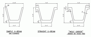
The design started with the simplest trapezoidal shape, but that shape was quickly abandoned. The lack of a top flange shifted the centroid of the girder excessively towards the bottom, and it was extremely difficult, if not impossible, to provide sufficient prestressing force to resist service conditions without damaging the girder during the prestressing process and erection. This established the need for top flanges and the “rabbit ears” option followed, with greater success. Top width of the section was driven by the minimum width of the guideway deck, and depth of the section and thickness of the flanges was optimized though iteration. While Arizona has not used precast trapezoidal box girders and has no standard shape, there are several states that have standardized these types of girders, including Colorado, Florida and Texas, with the Texas “tub-girders” being perhaps the most widely known. The design team decided to look at the possibility of using the standard Texas shape as an alternative to an all new customized shape. However, the team found that the standard Texas U-54 beam was a little too wide to fit two of them beneath the seventeen foot wide deck. The designer looked at using a narrower version of the U54 by removing a one foot width from the bottom flange, to match the width established in design of the rabbit-ears girder. This effort was not carried further since the capacity of the modified beam restricted the span lengths to 80 feet or less. Also, any cost savings from use of a standard shape would be lost if the forms had to be permanently modified.
The designers noted the details of the Texas U54 beam and decided to incorporate some of the details into the final custom shape, thus creating the final version of the girder that was subsequently nicknamed the “Wolf girder”, an internal joke on the name of this designer that was not adopted officially on the project. A key detail adopted from standardized sections was the chamfers in the top flange that facilitate stripping of the forms without damaging the concrete girder. The designers also drew on existing knowledge in standardized open girders when detailing mild steel reinforcement, skewed ends and spacing of internal diaphragms.
Comparison with AASHTO I-Girders
The Wolf girder is comparable to AASHTO Type IV and Type V girders, as seen in the Table.
The Wolf girder is about 25% heavier than an AASHTO Type IV but offers approximately 50% more capacity, for an overall 25% better strength to weight capacity. AASHTO Type V girders are approximately 15% more efficient than Wolf girders. However the alignment and column arrangement dictated by existing ground conditions did not allow for optimum span arrangement, and the Type V girders did not provide a saving over the Wolf girder. A preliminary estimate showed that that the elevated guideway would contain 19,000 LF of Type IV girders or 15,000 LF of Type V girders, but only 11,000 LF of Wolf girders.
Performance in Service
While the design used some standard geometry from Texas tub girders, the difference in depth and width of the Wolf girder precluded use of existing forms. US Concrete Precast Group, who won the contract to provide the 11,000 linear feet of Stage 1 girders, opted to use a custom built girder form. The self-stressing form provided the reaction to the prestress jacking force, eliminating the need for bulkheads. In the case of Stage 1A, the precaster, TPAC, used custom built conventional metal forms. The Wolf girder used only straight strands, with debonding at the ends to control initial stresses, and hence both precasters did not require hold-downs or a structural slab beneath the girder.
The casting and stressing of the girders was largely incident free. In the case of Stage 1 girders, the precaster used a high workability mix that facilitated placement of concrete. For Stage 1A, the project team allowed the use of Self Consolidating Concrete that had been recently approved for bridge girders by the Arizona Department of Transportation. In both cases the result was a high quality surface finish with minimal blemishes.
At this time, the Stage 1 girders have been in service for approximately 3 months, in addition to the period of systems testing, and have performed extremely well. Stage 1A girders were erected late in 2012 and the deck was cast earlier this year, with no notable problems reported in construction or performance.
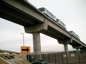
The Wolf Girder, the first major use of a precast open box girder in Arizona, was developed to meet a specific need on the Sky Train project and has performed as well as expected, blending structural efficiency and stability with an aesthetically pleasing form. This girder will be used not only on the upcoming Stage 2 of the Sky Train, but having proved its worth will hopefully be adopted for local projects in Phoenix and elsewhere in Arizona.▪


